A torque control method and system for a switched reluctance motor with current nonlinear compensation

A switched reluctance motor, nonlinear compensation technology, applied in control systems, AC motor control, electrical components and other directions, can solve the problem of inductance L is difficult to analyze, can not effectively suppress SRM torque ripple and other problems

Active Publication Date: 2018-03-16
GUILIN UNIV OF ELECTRONIC TECH
View PDF4 Cites 2 Cited by
  • Summary
  • Abstract
  • Description
  • Claims
  • Application Information

AI Technical Summary

Problems solved by technology

[0006] In fact, the inductance L of each phase of the switched reluctance motor changes with the change of the current I, and the relationship between torque and current is strongly nonlinear, making it difficult to analyze the inductance L
[0007] Therefore, the current control of the torque distribution function (TSF) of the switched reluctance motor is difficult to fundamentally solve the strong nonlinear relationship between torque and current, and it is still unable to effectively suppress the SRM torque ripple.

Method used


Image

  • A torque control method and system for a switched reluctance motor with current nonlinear compensation
  • A torque control method and system for a switched reluctance motor with current nonlinear compensation
  • A torque control method and system for a switched reluctance motor with current nonlinear compensation

Examples


Embodiment Construction

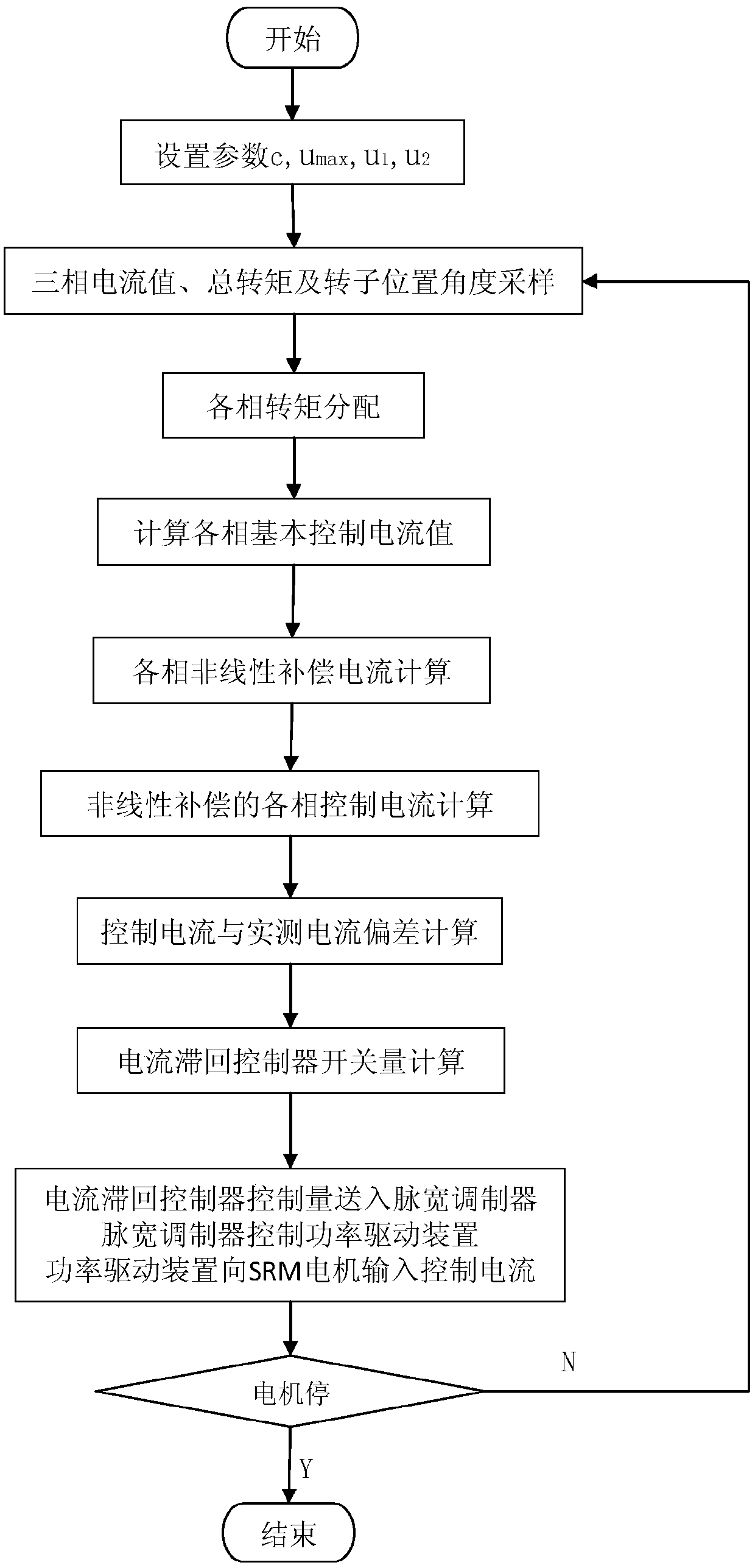
[0059] An embodiment of the torque control method for switched reluctance motors with current nonlinear compensation, the process is as follows figure 1 As shown, this example sets parameters c=0.2, u max =5v, u 1 =0.02, u 2 =-0.02, the actual measurement and sampling of the three-phase current value, total torque and rotor position angle of the switched reluctance motor SRM. The main steps are as follows:

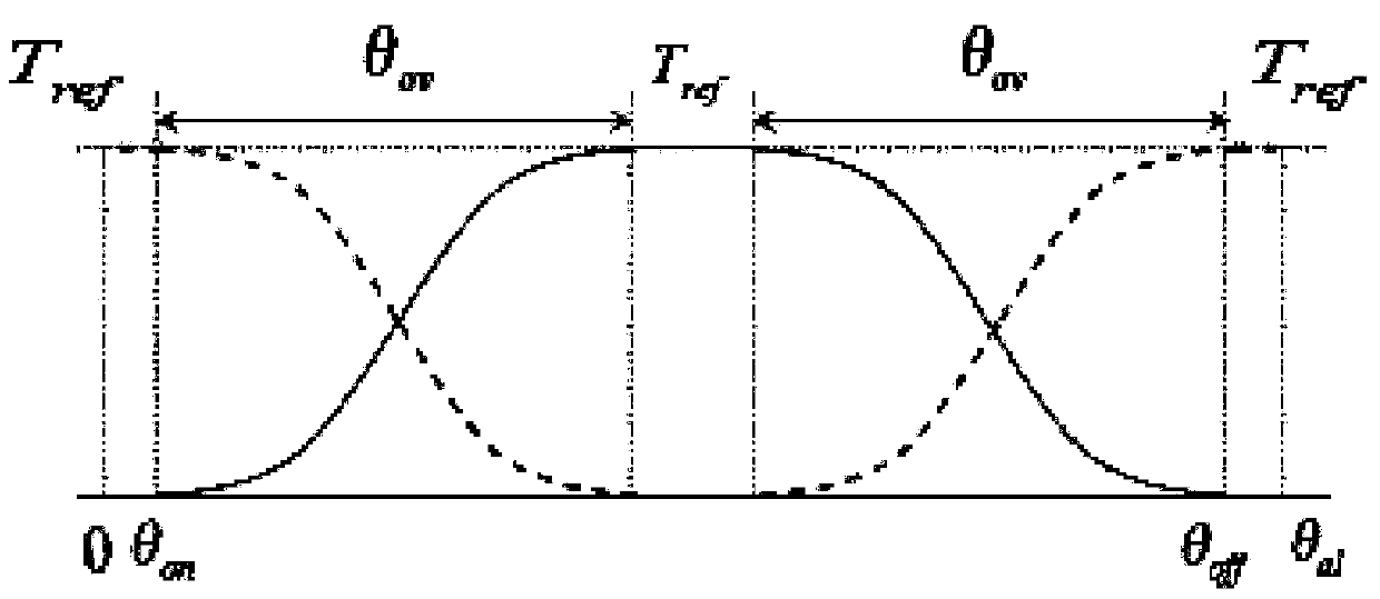
[0060] Ⅰ. Torque distribution of each phase according to the distribution function (TSF)

[0061] Select the cubic distribution function as the torque distribution function, as follows:

[0062]

[0063] Where θ is the rotor position angle, θ on is the opening angle, θ off is the breaking angle.

[0064] According to the distribution function will set the torque T ref Distributed to two adjacent phases, the distribution torque of one of the open phases is T up , the distribution torque of the other off-phase is T dn . Set the torque distribution as follows: ...


PUM


Abstract

The present invention is a switched reluctance motor torque control method and system with current nonlinear compensation, the method uses the electromagnetic torque mathematical expression of the switched reluctance motor linear inductance model to calculate the basic control current, and uses the optimal torque distribution function The set torque is allocated as the distribution torque of the on-phase and off-phase, and the basic control current of each phase is obtained by conversion; the nonlinear current compensation value of each phase is superimposed with the basic control current of each phase as the control current of each phase, and The deviation of the measured current controls the current hysteresis controller. The microprocessor of this system is connected with three current sensors and rotor position angle and torque sensors on the switched reluctance motor, and its program memory is equipped with a data acquisition module and each calculation module of the method, and the control signal is calculated according to each measured signal, The three-phase input current of the switched reluctance motor is controlled by a pulse width modulator. The invention effectively suppresses the torque ripple of the switched reluctance motor, can constitute an embedded system, and is convenient for on-line control.

Description

technical field [0001] The invention relates to the control field of an electric vehicle motor, in particular to a torque control method and system for a switched reluctance motor with current nonlinear compensation. Background technique [0002] Compared with other types of motors, switched reluctance motors (Switched Reluctance Motor, SRM) have the advantages of simple structure, firmness, no need for permanent magnet materials, high speed, reliable operation, and wide speed range, and have gradually become a research hotspot in the field of drive speed regulation. . However, the inherent double salient pole structure, highly nonlinear electromagnetic characteristics and switching power supply characteristics of the switched reluctance motor SRM lead to the torque ripple problem of the switched reluctance motor. Due to the strong nonlinearity of the electromagnetic characteristics of the switched reluctance motor, and there is no SRM mathematical model that meets the cont...

Claims


Application Information

Patent Timeline
Patent Type & Authority Patents(China)
IPC IPC(8): H02P25/098
Inventor 党选举姜辉伍锡如李珊张向文王涵正王月娥周芳莉朱国魂莫太平周子文
Owner GUILIN UNIV OF ELECTRONIC TECH
Why Eureka
Try Eureka