Special positioning fixture for blade numerical control precision machining

A precision machining and positioning fixture technology, which is applied in the field of mechanical parts processing, can solve problems such as blade flutter, and achieve the effects of ensuring machining accuracy, simplicity and compactness, and convenient and quick operation and disassembly

Inactive Publication Date: 2016-08-03
NORTHWESTERN POLYTECHNICAL UNIV
View PDF8 Cites 6 Cited by
  • Summary
  • Abstract
  • Description
  • Claims
  • Application Information

AI Technical Summary

Problems solved by technology

[0004] The purpose of the present invention is to provide a special positioning fixture for CNC precision machining of blades, which solves the problem of flutter during blade processing

Method used


Image

  • Special positioning fixture for blade numerical control precision machining
  • Special positioning fixture for blade numerical control precision machining
  • Special positioning fixture for blade numerical control precision machining

Examples


Embodiment Construction

[0016] The present invention will be described in detail below in conjunction with the accompanying drawings and specific embodiments.

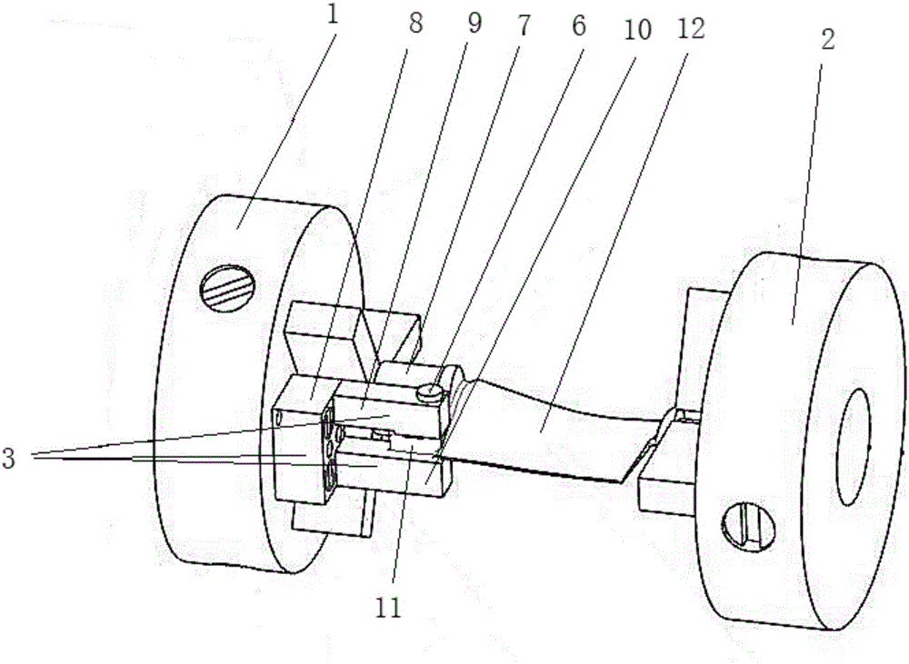
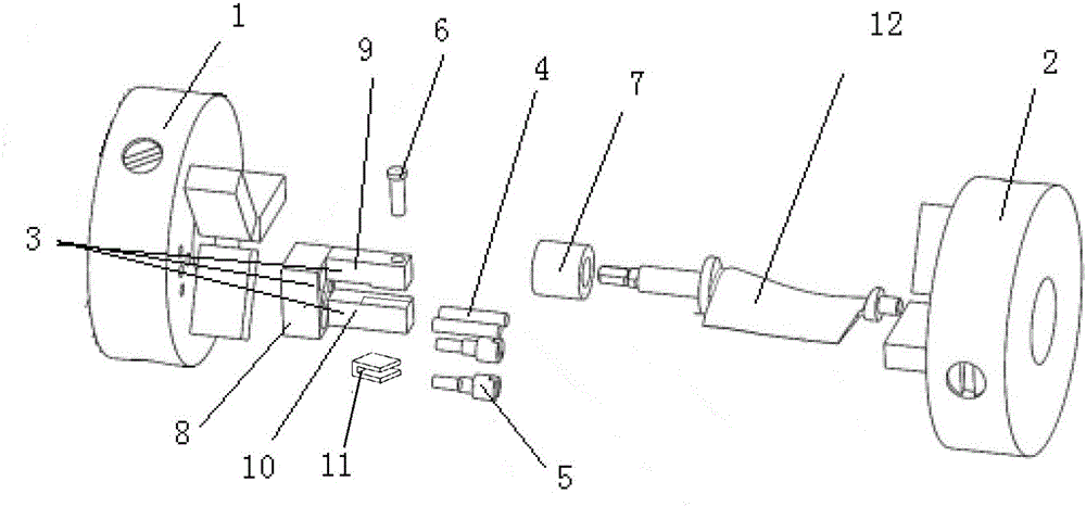
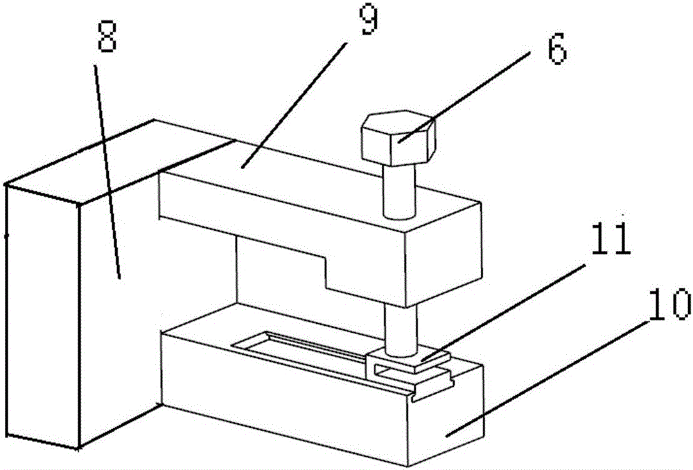
[0017] The invention provides a special positioning fixture for CNC precision machining of blades, such as figure 1 , figure 2 and image 3 As shown, it includes chuck a1 and chuck b2, chuck b2 is connected with the tailstock of the machine tool, chuck a1 is connected with the spindle head of the machine tool, and the end surface of chuck a1 is connected with chuck body 3 and retaining ring 7, chuck body 3 Located between the two claws of the chuck a1, the chuck body 3 includes a fixed block 8, on which the connecting rod b10 and the L-shaped connecting rod a9 are vertically connected, and the long side of the connecting rod a9 is parallel to the connecting rod b10, The short side of the connecting rod a9 is located between the long side of the connecting rod a9 and the connecting rod b10, the connecting rod a9 is provided with a fastening...


PUM


Abstract

The invention discloses a special positioning fixture for blade numerical control precision machining. The special positioning fixture comprises a chuck a and a chuck b, the chuck b is connected with a tailstock of a machine tool, the chuck a is connected with a main shaft head of the machine tool, a fixture body and a baffle ring are connected to the end face of the chuck a, and the fixture body is located between two clamping jaws of the chuck a and comprises a fixing block; and an L-shaped connecting rod a and a connecting rod b are vertically connected to the fixing block, a fastening screw is arranged on the connecting rod a, the connecting rod b is provided with a sliding block sliding along the connecting rod b, and the sliding block is located between the connecting rod a and the connecting rod b. When the special positioning fixture for blade numerical control precision machining is used, it is guaranteed that the blade and the main shaft of the machine tool are coaxial; the two ends of the blade are fastened to solve the problems of chattering caused by dynamic cutting force in the cutting process and deformation caused in the machining process. The special positioning fixture is simple and compact in structure, high in positioning accuracy, rapid and convenient to operate and demount, and capable of effectively guaranteeing the machining accuracy of the front face and the back face of the blade.

Description

technical field [0001] The invention belongs to the technical field of mechanical parts processing, and relates to a special positioning fixture for numerical control precision machining of blades. Background technique [0002] Blades are key parts of industrial turbines such as aero-engines, compressors, axial fans, and gas turbines, and are widely used in fields such as energy and power, rail transit, petrochemical, and national defense. The level of blade manufacturing reflects the comprehensive level of metallurgical materials, processing equipment, design and process technology in a country's manufacturing industry. Blades are not only characterized by complex curved surfaces, large torsion angles, and difficult forming. Processing requires a machining center with more than 4 coordinates, and most of the materials are stainless steel and titanium alloys that are difficult to process. According to different industries, they have many types, large quantities, complex shap...

Claims


Application Information

Patent Timeline
Patent Type & Authority Applications(China)
IPC IPC(8): B23Q3/06
CPCB23Q3/063
Inventor 田卫军任军学李郁姚倡锋冯亚洲周金华
Owner NORTHWESTERN POLYTECHNICAL UNIV
Why Eureka
Try Eureka