Splitting machine

A technology of slitting machine and slitting roller, which is applied in the direction of winding strips, sending objects, thin material processing, etc., which can solve the problems of affecting product appearance and use effect, reducing the friction coefficient between guide rollers and cork surface Particles fall and other problems, to achieve good flattening effect, increase the speed of rotation, easy to clean and hygienic

Inactive Publication Date: 2016-08-03
SHANGHAI HERO CHAMPION COATING TECH
View PDF0 Cites 3 Cited by
  • Summary
  • Abstract
  • Description
  • Claims
  • Application Information

AI Technical Summary

Problems solved by technology

[0002] At present, the slitters on the market have low operating speed and poor controllability. The winding parts of the original slitting machines are all pasted with ordinary cork on the aluminum guide rollers. The winding speed of the equipment is generally only 300m / min. The range of the production efficiency cannot be improved. The surface of cork stickers will heat up when they are often operated on the guide roller for a long time. During the production process, particles on the surface of cork stickers will fall, and particles falling in the product will directly affect The hygienic use of the product will also reduce the friction coefficient between the guide roller and the guide roller. When the product passes through the surface, it will cause slippage and cause scratches on the aluminum-plated surface, which directly affects the appearance and use effect of the product.

Method used


Image

  • Splitting machine
  • Splitting machine
  • Splitting machine

Examples


Embodiment Construction

[0014] The following will clearly and completely describe the technical solutions in the embodiments of the present invention with reference to the accompanying drawings in the embodiments of the present invention. Obviously, the described embodiments are only some, not all, embodiments of the present invention. Based on the embodiments of the present invention, all other embodiments obtained by persons of ordinary skill in the art without making creative efforts belong to the protection scope of the present invention.

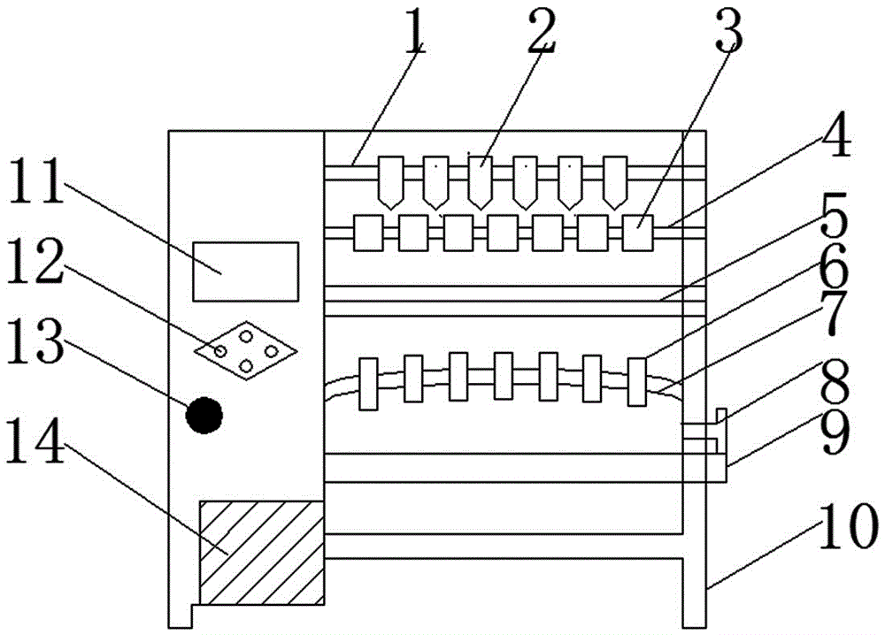
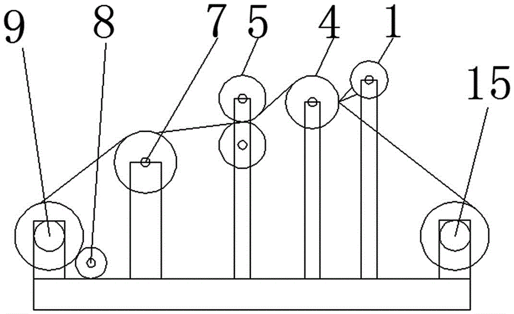
[0015] see Figure 1-3 , an embodiment provided by the present invention: a slitting machine, including a slitting roller 1, a slitting shaft 4, a pressure roller 5, a retardation disc 8, a control panel 12, a motor 14 and a winding 15, the slitting roller 1 is equipped with a slitting knife 2, the slitting shaft 4 is arranged below the slitting roller 1, and a collar 3 is installed on the slitting shaft 4, and the pressing roller 5 is installed on the left si...


PUM


Abstract

The invention discloses a slitting machine, which comprises a slitting roller, a slitting shaft, a pressure roller, a retardation plate, a control panel, a motor and a winding, a slitting knife is installed on the slitting roller, and a slitting knife is installed on the slitting roller. The shaft is arranged below the slitting roller, and a collar is installed on the slitting shaft, the pressure roller is installed on the left side of the slitting shaft, and an arc roller is installed on the lower left of the pressure roller, and the arc roller Rollers are installed, and an unwinding device is installed on the lower left side of the arc roller. The unwinding device is connected to the frame through bearings. A motor is installed on the left side of the frame, and a switch is arranged above the motor. The winding is installed on the frame, and the aluminum guide roller is installed on the winding, and the nitrile rubber coating is fixed on the aluminum guide roller. The slitting machine of the present invention is equipped with a new type of rubber roller, which is easy to clean and hygienic, and is not easy to be worn out. The density of the aluminum layer is well protected, and the flattening effect is better, so that the quality and efficiency of the product are greatly improved.

Description

technical field [0001] The invention relates to the technical field of slitter equipment, in particular to a slitter. Background technique [0002] At present, the slitters on the market have low operating speed and poor controllability. The winding parts of the original slitting machines are all pasted with ordinary cork on the aluminum guide rollers. The winding speed of the equipment is generally only 300m / min. The range of the production efficiency cannot be improved. The surface of cork stickers will heat up when they are often operated on the guide roller for a long time. During the production process, particles on the surface of cork stickers will fall, and particles falling in the product will directly affect The hygienic use of the product will also reduce the friction coefficient between the guide roller and the guide roller. When the product passes the surface, it will cause slippage and cause scratches on the aluminum-plated surface, which directly affects the ap...

Claims


Application Information

Patent Timeline
Patent Type & Authority Applications(China)
IPC IPC(8): B65H23/34B65H27/00B65H23/182B65H35/02
CPCB65H23/34B65H23/1825B65H27/00B65H35/02B65H2701/1133B65H2701/1752
Inventor 曾文东陈中修陈中翰
Owner SHANGHAI HERO CHAMPION COATING TECH
Why Eureka
Try Eureka