Electric deposition device for preparing high-resolution alpha source

An electrodeposition device and high-resolution technology, which is applied in the electrolysis process, electrolysis components, plating tanks, etc., can solve the problems of preparing high-resolution α sources, and achieve the effects of accelerated ion movement, small deposition thickness, and dense coating

Active Publication Date: 2016-08-03
CHINA INSTITUTE OF ATOMIC ENERGY
View PDF3 Cites 17 Cited by
  • Summary
  • Abstract
  • Description
  • Claims
  • Application Information

AI Technical Summary

Problems solved by technology

At present, there is no report in the open literature on the pr...

Method used


Image

  • Electric deposition device for preparing high-resolution alpha source
  • Electric deposition device for preparing high-resolution alpha source
  • Electric deposition device for preparing high-resolution alpha source

Examples


Embodiment 1

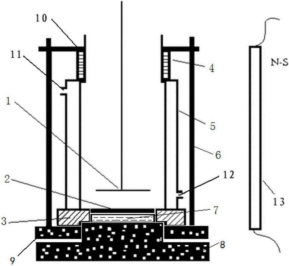
[0035] An electrodeposition device for preparing a high-resolution α source, the electrodeposition device includes a DC stabilized power supply, an electroplating tank 5, a bottom scale 2 made of stainless steel, a magnet 13 and a platinum electrode 1; the electroplating tank 5 The material is glass, which is a two-layer structure inside and outside, and the upper and bottom of the inner layer are provided with openings; the inner layer of the electroplating tank 5 is used to hold the electrodeposition plating solution, and the lower right corner of the outer layer is provided with a cooling circulating water inlet 12 , the upper left corner is provided with a cooling circulating water outlet 11; between the inner wall of the outer layer and the outer wall of the inner layer is the channel through which the cooling circulating water flows; the platinum electrode 1 is connected to the stirring motor, and the rotating speed of the platinum electrode 1 during the electrodeposition ...

Embodiment 2

[0044]Different from Example 1, the platinum electrode 1 extends from the radial center position of the upper end of the electroplating tank 5 to a position 1 cm away from the bottom of the electroplating tank; the bottom 2 is called silver; 1 at 60 rpm.

[0045] The magnetic field strength of the radial magnet relative to the center of the electroplating tank is 0.6T, and the distance from one side of the electroplating tank 5 is 3 cm.

Embodiment 3

[0047] Different from Example 1, the platinum electrode 1 extends from the radial center position of the upper end of the electroplating tank to the position 0.8 cm away from the bottom of the electroplating tank; the bottom 2 is aluminum; 1 at 50 rpm.

[0048] The magnetic field strength of the radial magnet relative to the center of the electroplating tank 1 is 1T, and the distance from one side of the electroplating tank is 1 cm.


PUM


Abstract

The invention belongs to the technical field of preparation of radioactive sources, and discloses an electric deposition device for preparing a high-resolution alpha source. The electric deposition device comprises a power supply, an electric plating tank, a bottom weigher, a magnet and a platinum electrode; the electric plating tank is of a two-layer structure with an inner layer and an outer layer; openings are formed in the upper end and the bottom of the inner layer; the inner layer of the electric plating tank is used for accommodating electric deposition plating liquid; a cooling circulating water inlet and a cooling circulating water outlet are formed in opposite angles of the outer layer; an upper sealing ring and an upper sealing cover on the upper side are arranged in the opening in the upper end of the inner layer; a lower sealing ring and a lower sealing cover on the lower side are arranged in the opening in the bottom of the inner layer; the bottom weigher serves as a cathode, and is tightly attached to the lower portion of a hole way in middle of the lower sealing ring; and the platinum electrode extends from the radial center position of the upper end of the inner layer of the electric plating tank to a position 0.5-1 cm away from the bottom of the electric plating tank. The alpha source prepared by the device has the beneficial effects of high electric deposition efficiency, a compact plating layer, good uniformity and low deposition thickness.

Description

technical field [0001] The invention belongs to the technical field of radioactive source preparation, and in particular relates to an electrodeposition device for preparing a high-resolution alpha source. Background technique [0002] Some α-nuclides in environmental radioactivity monitoring and nuclear accident emergency monitoring have a special status in the impact of nuclear accidents on the environment and the formulation of radioactive pollution disposal programs because of their strong toxicity and very long half-life. The migration content of such α-nuclides in the surrounding environment samples after the accident release is very low, and it is difficult to measure directly with instruments. The difficulty in determination is not only low content, easy loss during sample preparation, and cross-contamination by other α-nuclides, but also because they have complex and changeable chemical forms under complex ecological conditions. Relatively speaking, the easiest and...

Claims


Application Information

Patent Timeline
IPC IPC(8): C25D17/00C25D17/02
CPCC25D17/00C25D17/02
Inventor 徐利军叶宏生林敏张卫东夏文陈克胜陈义珍
Owner CHINA INSTITUTE OF ATOMIC ENERGY
Why Eureka
Try Eureka