High strength combination column

A high-strength, composite column technology, applied in the field of composite columns, can solve problems such as heavy weight, complex structure, and difficult assembly, and achieve the effects of light weight, flexible installation, and high versatility

Inactive Publication Date: 2016-08-03
黄通
View PDF9 Cites 1 Cited by
  • Summary
  • Abstract
  • Description
  • Claims
  • Application Information

AI Technical Summary

Problems solved by technology

The shapes of the composite columns in the above technical solutions are all fixed, and composite columns of various shapes are designed according to the construction needs of the building, and the structure of the composite columns is complex, heavy and difficult to assemble

Method used


Image

  • High strength combination column
  • High strength combination column
  • High strength combination column

Examples


Embodiment Construction

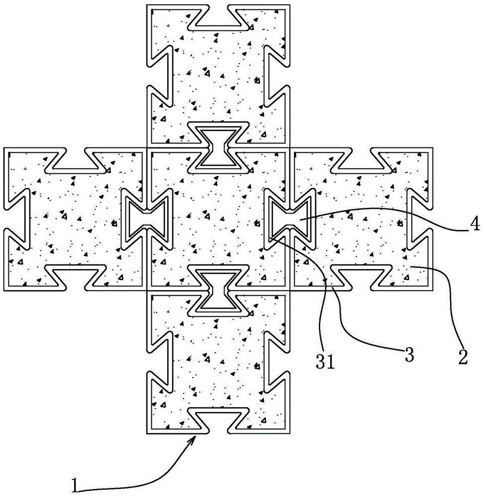
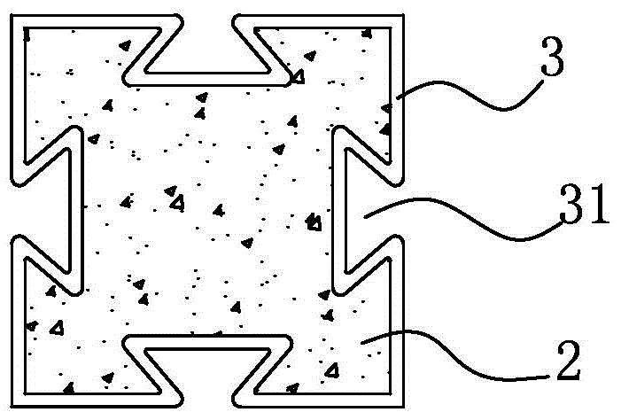
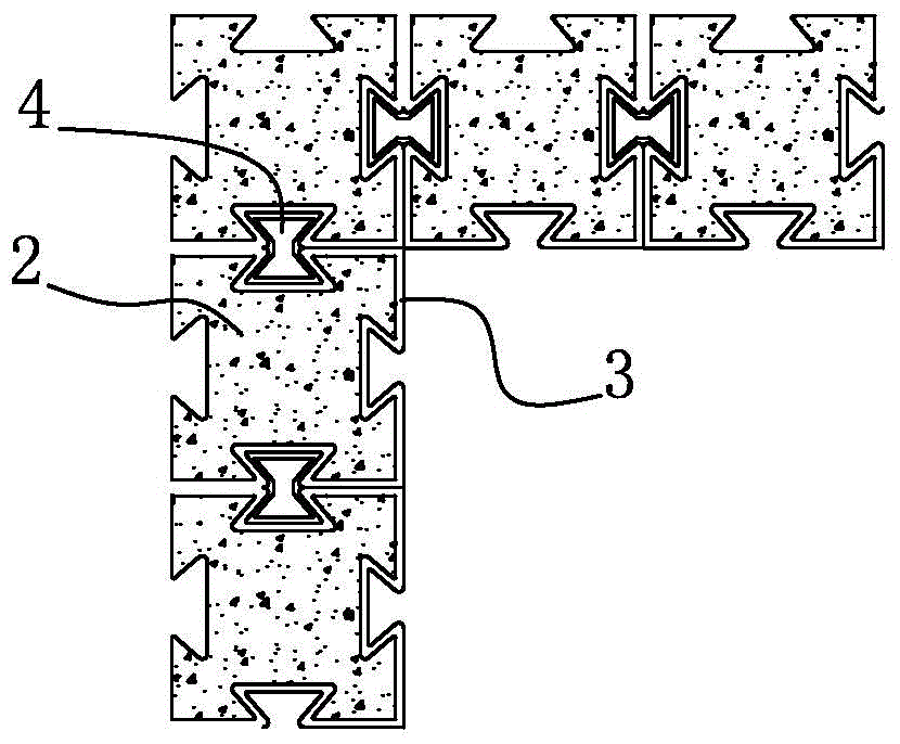
[0019] see figure 1 and figure 2 In the embodiment of a high-strength composite column given in the present invention, it includes a high-strength keel 1 made of metal materials and a filling material 2, the keel 1 is spliced ​​by a plurality of basic parts 3, and the basic The part 3 is a hollow cylindrical structure, and the adjacent basic parts 3 are connected together, and the cavity of the basic part 3 is filled with the filling material 2 . The keel 1 in the present invention has relatively high strength, which is equivalent to or higher than that of traditional reinforced concrete composite columns, that is, the keel can meet the strength requirements of the composite column. The basic element 3 is a basic unit constituting a composite column, and a plurality of basic elements 3 are used to connect together to form a required composite column according to the design strength requirements and shape. The weight of a single basic component 3 is relatively light, which i...


PUM


Abstract

The invention provides a high strength combination column, includes high strength fossil fragments and filling material that metal material made, its characterized in that: fossil fragments are formed by the concatenation of a plurality of bare bones, said bare bones is cavity cylindricality structure, and is adjacent the bare bones links together, fill in the cavity of bare bones said filling material. The high strength combination column has the advantages of light weight, flexible installation, fire prevention and warm insulation, and low cost.

Description

technical field [0001] The invention relates to a composite column for buildings, in particular to a high-strength composite column. Background technique [0002] Columns in the prior art are generally made of steel bars and concrete. Such walls are relatively heavy and require on-site pouring, which is difficult for prefabrication. In order to overcome the problem of prefabrication, various forms of composite columns have appeared in the prior art. For example, the invention patent with the Chinese patent number CN201210051715.0, whose disclosure date is July 8, 2012, discloses a combined prefabricated column with nodes, which is characterized in that it includes a column and nodes, and the nodes are arranged on the upper and lower sides of the column At both ends and an integer multiple of the storey height, the column includes a bottom column, a middle column and a top column connected in sequence, the column of the bottom column is made of engineering fiber cement-based...

Claims


Application Information

Patent Timeline
Patent Type & Authority Applications(China)
IPC IPC(8): E04C3/34
Inventor 黄通张记会王秀杰黄书亮
Owner 黄通
Why Eureka
Try Eureka