Synchronizer and gearbox

A synchronizer and synchronizing ring technology, which is applied in the field of gearboxes, can solve the problems such as the reduction of transmission shifting efficiency, the reduction of transmission transmission efficiency, and the aggravation of 1' wear of the synchronizing ring, and the effects of easy processing, reasonable structure and cost control are achieved.

Active Publication Date: 2016-08-03
ZHEJIANG WANGLIYANG TRANMISSION CO LTD
View PDF5 Cites 3 Cited by
  • Summary
  • Abstract
  • Description
  • Claims
  • Application Information

AI Technical Summary

Problems solved by technology

[0002] The structure of the existing synchronizer is as figure 1 As shown, the synchronous ring 1' has a large free space in the axial direction of the synchronizer, and it is easy to get close to the coupling tooth 2' uncontrollably, resulting in the friction cone surface of the synchronous ring 1' and the friction cone of th

Method used


Image

  • Synchronizer and gearbox
  • Synchronizer and gearbox

Examples


Example Embodiment

[0040] Embodiment one:

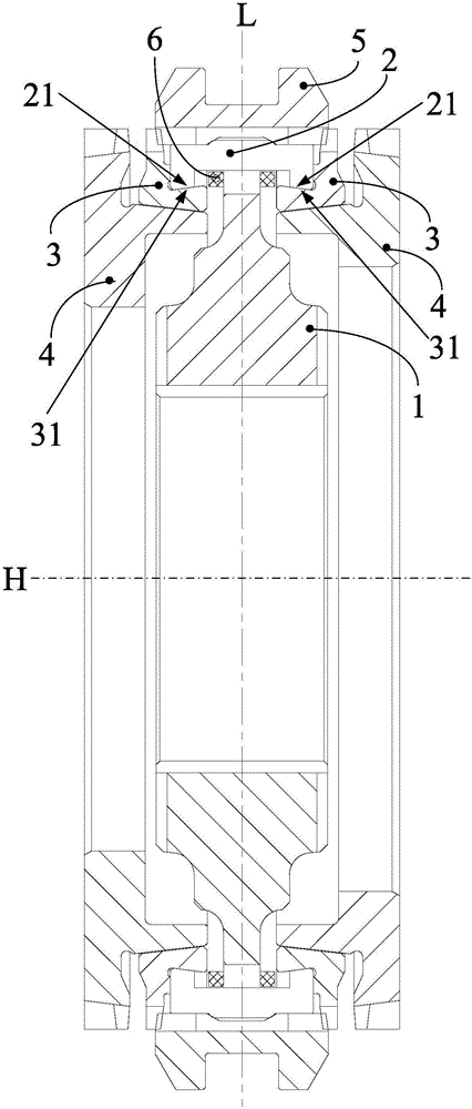
[0041] The accommodating groove includes a side wall arranged along the circumference of the synchronization ring 3 and a top wall facing the axial center of the synchronizer, such as figure 2As shown, L is the axial centerline of the synchronizer, the slider 2 is in conflict with the top wall and the side wall of the housing groove, and the slider 2 and the side wall of the housing groove are axially limited through taper fit; wherein, the first limit One of the position part 21 and the second limit part 31 is an outwardly convex conical arc surface, and the other is an inner concave conical arc surface, and the outer convex conical arc surface and the inner concave conical arc surface reach the axis H of the synchronizer The distance from the end close to the axial center of the synchronizer gradually decreases to the end far away from the axial center of the synchronizer.

[0042] In this solution, the slider 2 is in conflict with the top wall of ...

Example Embodiment

[0045] Embodiment two: (not shown in the figure)

[0046] One of the first limiting part and the second limiting part is a bar-shaped chute arranged along the circumference of the synchronous ring, and the other is a limiting slider. The limiting slider is inserted into the bar-shaped chute and can slide relative to the bar. The groove slides along the circumferential direction of the synchronizer, and the width of the limit slider is equal to or close to the width of the bar slide groove.

[0047] In this scheme, one of the side walls of the slider and the receiving groove is provided with a bar-shaped chute, and the other is provided with a limit slider. The limit slider can slide relative to the bar-shaped chute along the circumferential direction of the synchronizer to ensure synchronization. The device can work normally, and the width of the limit slider is equal to or close to the width of the bar chute, which eliminates the free space for the axial movement of the synch...


PUM


Abstract

The invention provides a synchronizer and a gearbox. The synchronizer comprises toothholders, sliding blocks arranged on the outer ring face of the toothholders and provided with first limiting parts, connecting teeth provided with outer conical faces, synchronizing rings capable of moving in the axial direction relative to the connecting teeth and provided with conical holes capable of being matched with the outer conical faces and containing grooves capable of being matched with the sliding blocks, and tooth sleeves capable of being engaged with the connecting teeth and the synchronizing rings, wherein the sliding blocks can slide in the circumferential direction relative to the containing grooves, and the groove walls of the containing grooves are provided with second limiting parts. In the technical scheme, free movement spaces of the synchronizing rings in the axial direction are eliminated through matching of the first limiting parts and the second limiting parts, the axial synchronous movement of the synchronizing rings and the sliding blocks during gear shifting is achieved, the synchronizing rings are prevented from attaching to the connecting teeth uncontrollably, and the problem of large-area friction of the friction conical faces of the synchronizing rings and the friction conical faces of the connecting teeth is avoided, so that the gear-shifting efficiency of the gearbox is improved, abrasion to the synchronizing rings is reduced, and the service life of the synchronizing rings is prolonged.

Description

technical field [0001] The invention relates to the field of automobile manufacturing, more specifically, to a synchronizer and a gearbox with the synchronizer. Background technique [0002] The structure of the existing synchronizer is as figure 1 As shown, the synchronous ring 1' has a large free space in the axial direction of the synchronizer, and it is easy to get close to the coupling tooth 2' uncontrollably, resulting in the friction cone surface of the synchronous ring 1' and the friction cone of the coupling tooth 2' The problem of large-area friction occurs on the surface, which will not only reduce the transmission efficiency of the transmission, resulting in a decrease in the shifting efficiency of the transmission, but also aggravate the wear of the synchronous ring 1' and shorten the life of the synchronous ring 1'. Contents of the invention [0003] The present invention aims to solve at least one of the technical problems existing in the prior art. [000...

Claims


Application Information

Patent Timeline
IPC IPC(8): F16D23/02
CPCF16D23/025F16D2023/0631
Inventor 乔湘鹤程森苏亮李小建周德龙叶伟飞陈红芳
Owner ZHEJIANG WANGLIYANG TRANMISSION CO LTD
Why Eureka
Try Eureka