
Laser phase range finding method

A phase ranging and laser technology, which is used in measurement devices, radio wave measurement systems, and re-radiation of electromagnetic waves. It can solve the problems of poor ranging accuracy and unstable ranging, and achieve the effect of eliminating phase errors.

Active Publication Date: 2016-08-03
SHENZHEN WEIRUI JINGKE ELECTRONICS
View PDF4 Cites 9 Cited by
  • Summary
  • Abstract
  • Description
  • Claims
  • Application Information

AI Technical Summary

Problems solved by technology

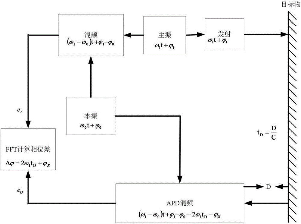
[0003] like figure 2 , taking single emission and single reception as an example, the measurement method of single emission and single reception introduces a phase error in the actual measurement However, when the single optical path eliminates the above-mentioned phase error, a large number of experiments are required to simulate the data of the phase error caused by various environments, and the algorithm is used to correct the measured value according to the experimental data to make the measured data accurate; but the measurement environment is ever-changing, It is impossible to obtain so much experimental data through experiments, so single transmission and single reception show some shortcomings in eliminating phase errors in real time, and using experimental data to eliminate phase errors may cause instability in ranging in unfamiliar environments and ranging accuracy

Method used


Image

  • Laser phase range finding method
  • Laser phase range finding method
  • Laser phase range finding method

Examples


Embodiment Construction

[0043] The following will clearly and completely describe the technical solutions in the embodiments of the present invention with reference to the accompanying drawings in the embodiments of the present invention. Obviously, the described embodiments are only some, not all, embodiments of the present invention. Based on the embodiments of the present invention, all other embodiments obtained by persons of ordinary skill in the art without making creative efforts belong to the protection scope of the present invention.

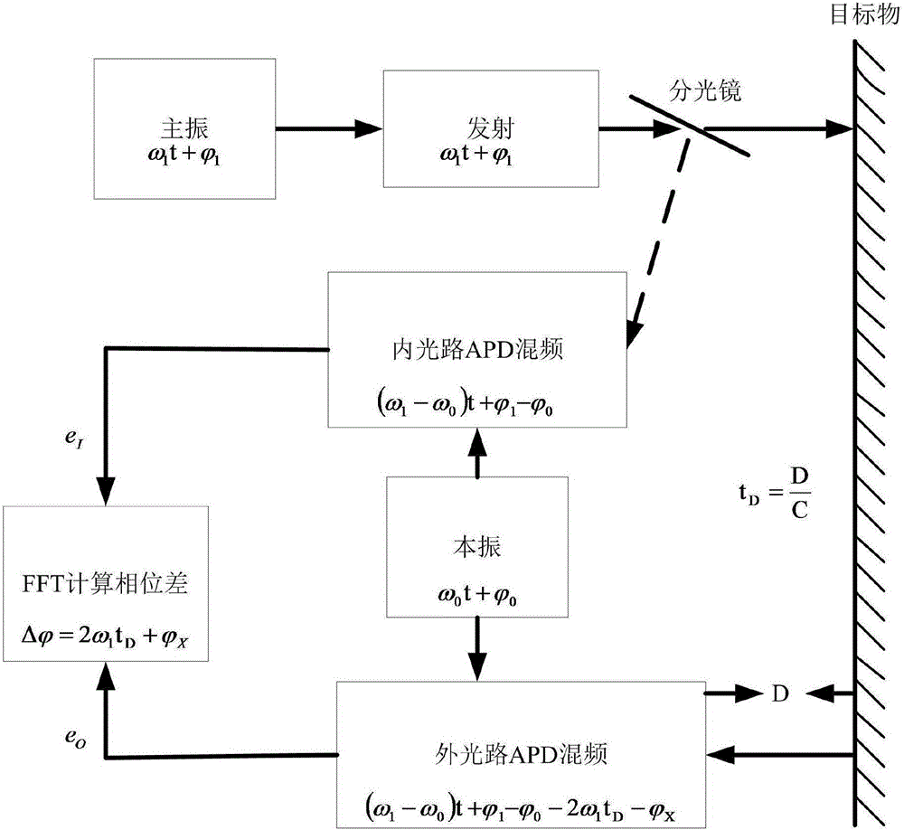
[0044] The purpose of the present invention is to provide a laser phase ranging method to solve the problems of the above-mentioned prior art, utilize the stability of the internal optical path, eliminate the phase error caused by different environments and conditions in real time, and improve the stability and accuracy of ranging. Accuracy; AGC circuit and second-order band-pass filter circuit are used to improve the signal-to-noise ratio of the ranging signal...


PUM


Abstract

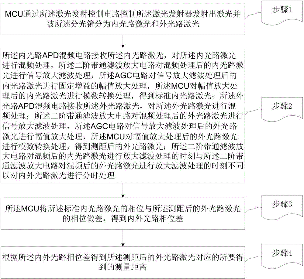
A laser phase range finding method disclosed by the present invention comprises the steps of dividing the laser emitted out by a spectroscope into the inner light path laser and the outer light path laser; using an inner / outer light path APD mixer circuit to carry out the mixing processing on the inner light path laser and the outer light path laser separately, using a second-order band-pass filtering amplifying circuit to carry out the signal amplifying and filtering processing on the inner light path laser and the outer light path laser after the mixing processing in a time sharing manner, using an AGC circuit to carry out the amplitude amplification processing on the inner light path laser and the outer light path laser after the amplification and filtering processing separately, using an MCU to obtain the phase difference of the inner light path laser and the outer light path laser after the amplitude amplification processing, and obtaining the measurement distance corresponding to the outer light path laser after the range finding according to the phase difference of the inner and outer light paths. The beneficial effects of the present invention are that a total phase error caused under different environments is eliminated real-timely, so that the range finding stability and precision are improved; the AGC circuit and the second-order band-pass filtering amplifying circuit are utilized simultaneously to improve the amplitude and the signal to noise ratio of a signal, so that the phase difference operation is more accurate.

Description

technical field [0001] The invention relates to the field of laser ranging, in particular to a laser phase ranging method. Background technique [0002] Laser phase rangefinders currently on the market are roughly divided into three types according to the measurement optical path: single emission and single reception, single emission and single reception (using motor switching to achieve dual optical paths), double emission and single reception, and double emission and double reception. But each has its own advantages and disadvantages. [0003] Such as figure 2 , taking single emission and single reception as an example, the measurement method of single emission and single reception introduces a phase error in the actual measurement However, when the single optical path eliminates the above-mentioned phase error, a large number of experiments are required to simulate the data of the phase error caused by various environments, and the algorithm is used to correct the meas...

Claims


Application Information

Patent Timeline
IPC IPC(8): G01S17/08
CPCG01S17/08
Inventor 王永红
Owner SHENZHEN WEIRUI JINGKE ELECTRONICS
Learn More