Method for establishing internal leakage model of vane type continuous rotary electro-hydraulic servomotor

An electro-hydraulic servo and vane-type technology, applied in the direction of electric digital data processing, special data processing applications, instruments, etc., can solve the problems of great difference, staying, and not considering the key parts of the motor, etc., to achieve low-speed performance improvement and overall structure Optimization and improvement, the effect of important practical value

Inactive Publication Date: 2016-08-03
HARBIN UNIV OF SCI & TECH
View PDF3 Cites 7 Cited by
  • Summary
  • Abstract
  • Description
  • Claims
  • Application Information

AI Technical Summary

Problems solved by technology

[0003] Leakage can be divided into internal leakage and external leakage. For the vane-type continuous rotary electro-hydraulic servo motor, the situation of external leakage is more complicated. At present, most of the research on the internal leakage of electro-hydraulic servo motors stays at the level of theoretical derivation. The clearance of key components is calculated according to a fixed value, and the influence of deformation of key components of the motor on internal leakage under different working conditions is not considered, which makes the theoretical calculation results far from the actual situation

Method used


Image

  • Method for establishing internal leakage model of vane type continuous rotary electro-hydraulic servomotor
  • Method for establishing internal leakage model of vane type continuous rotary electro-hydraulic servomotor
  • Method for establishing internal leakage model of vane type continuous rotary electro-hydraulic servomotor

Examples


Embodiment Construction

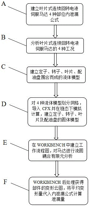
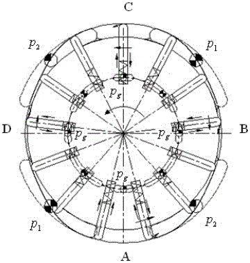
[0018] In order to ensure the flexible operation of the blade type continuous rotary electro-hydraulic servo motor, there must be a certain gap between the relative sliding surfaces of each component. When these gaps are under the action of the pressure difference between the high and low pressure chambers, internal leakage will inevitably occur, and the internal leakage mainly includes:

[0019] (1) Leakage between the top of the blade and the inner surface of the stator;

[0020] (2) Leakage between the end surface of the blade and the working surface of the oil distribution plate;

[0021] (3) Leakage of the matching gap between the blade and the blade groove;

[0022] (4) Leakage between the end face of the rotor and the working face of the oil distribution plate.

[0023] After careful analysis and reasonable simplification, these four kinds of leakage can be classified as parallel plane gap leakage.

[0024] The parameters of the vane type continuous rotary electro-hy...


PUM


Abstract

The invention discloses a method for establishing an internal leakage model of a vane type continuous rotary electro-hydraulic servomotor. The invention is intended to fill a blank field of an internal leakage mathematic model, which is based on numerical simulation and theoretical calculation in a micro clearance and in different working conditions, of the vane type continuous rotary electro-hydraulic servomotor, so as to establish an internal leakage model of a motor. The method for establishing the internal leakage model of the vane type continuous rotary electro-hydraulic servomotor comprises the following steps: step A, establishing internal leakage formulas of four positions of the motor; step B, analyzing four working conditions of the motor; step C, establishing a fluid model formed by enclosing a stator, a rotor, a vane and an oil distribution disc; step D, carrying out grid division on the four fluid models by using CFD (Computational Fluid Dynamics) software, importing files in CFX (Computational Fluid X) to simulate calculation in a stable state, and establishing solid models of the stator, the rotor, the vane and the oil distribution disc; step E, establishing a workflow chart in a WORKBENCH, and carrying out fluid-solid coupling analysis on the motor; step F, obtaining aberration nephograms of all components through the post processing by the WORKBENCH, substituting aberration nephograms of all the components into the corresponding formulas in step A, so that a leakage amount caused by an initial clearance and solid-fluid coupling deformation can be obtained.

Description

technical field [0001] The invention belongs to the field of electro-hydraulic servo motors, in particular to a method for establishing an internal leakage model of a vane-type continuous-rotation electro-hydraulic servo motor. Background technique [0002] With the development of the economic level and the continuous enhancement of national defense strength, my country has made great progress in the fields of aviation, aerospace and related science and technology. At the same time, it has also put forward stricter requirements for the precision and controllability of exploration tools and aircraft. The simulation turntable is a high-precision key equipment for ground hardware-in-the-loop simulation during the development of missiles and other aircraft. It is directly driven by electro-hydraulic servo motors. The high-precision simulation turntable has strict requirements on low-speed performance, and the leakage of the continuous rotation electro-hydraulic servo motor will ...

Claims


Application Information

Patent Timeline
Patent Type & Authority Applications(China)
IPC IPC(8): G06F17/50
CPCG06F30/367
Inventor 王晓晶李嵩洗昌富满国佳张梦俭
Owner HARBIN UNIV OF SCI & TECH
Why Eureka
Try Eureka