
Finishing device and method for machining shaft axial bearings

A thrust bearing and finishing technology, which is applied in superfinishing machines, metal processing equipment, manufacturing tools, etc., can solve problems such as unfavorable device costs, and achieve the effects of simple compensation, cost reduction, and high cutting speed

Active Publication Date: 2016-08-03
SUPFINA GRIESHABER
View PDF6 Cites 0 Cited by
  • Summary
  • Abstract
  • Description
  • Claims
  • Application Information

AI Technical Summary

Problems solved by technology

The resulting equipment costs are acceptable for large batches (that is to say for a large number of identical crankshafts following each other) to be machined; Between, the device cost is unfavorable and results in a significant portion of non-productive additional operating time

Method used


Image

  • Finishing device and method for machining shaft axial bearings
  • Finishing device and method for machining shaft axial bearings

Examples


Embodiment Construction

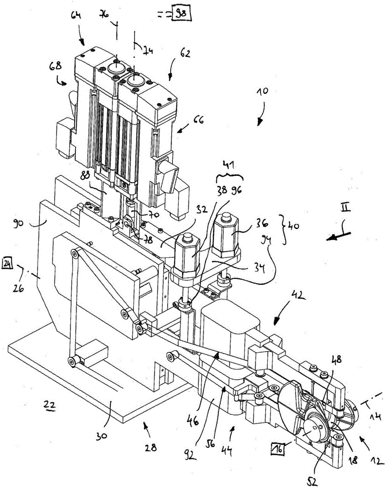
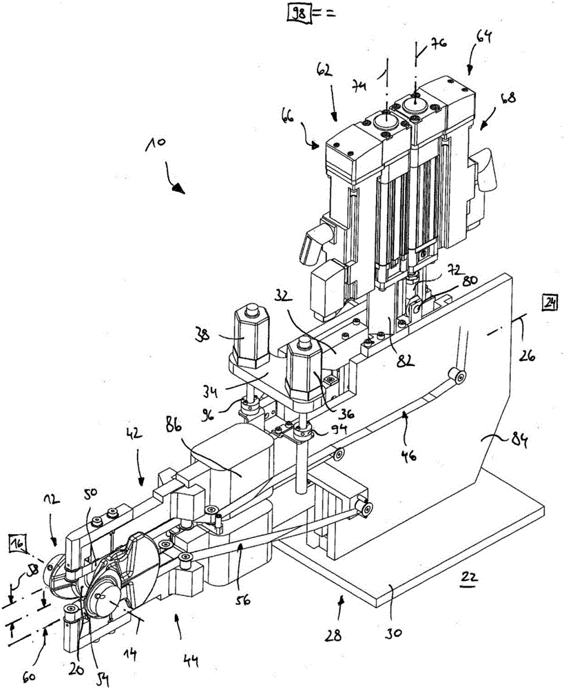
[0027] figure 1 and 2 One embodiment of the finishing device is shown from various angles and is generally designated 10 . The finishing device 10 is used for finishing the thrust bearing surface of a workpiece 12 , which is in particular configured as a crankshaft. The workpiece 12 has an axis 14 . During machining of the workpiece 12 , the workpiece is driven by a schematically shown rotary drive 16 so that the workpiece 12 is rotated about the workpiece axis 14 .

[0028] The workpiece 12 has at least one, preferably two, thrust bearing surfaces 18 and 20 to be machined. The thrust bearing surfaces 18 and 20 together form a crankshaft flange bearing which, when installed in an internal combustion engine, serves to support the crankshaft axially.

[0029] The finishing device 10 is arranged on a known and not shown machine frame 22 . Here, the finishing device 10 is fixed to the machine frame 22 or driven to oscillate along an oscillation axis 26 by a known and schemati...


PUM


Abstract

The invention relates to a finishing device (10) for machining shaft axial bearings, in particular crankshaft flange bearings, comprising a retainer (28) which is arranged or can be arranged on a machine frame (22), on which retainer a machining unit (42) comprising a finishing tool (56) is moveably mounted, wherein a movement of the machining unit (42) is associated with an adjustment of a diameter of a shaft axial bearing to be processed by means of the finishing tool (46), wherein a motorized drive unit (62) which drives the processing unit (42) along an adjustment axis (74) is provided for moving the processing unit (42). The invention further relates to a method for machining shaft axial bearings.

Description

technical field [0001] The invention relates to a finishing device for machining a shaft thrust bearing, in particular a crankshaft flange bearing, comprising a holder which is arranged or can be arranged on a frame, on which a movable A machining unit including a finishing tool is mounted, wherein movement of the machining unit is associated with adjustment of the diameter of the shaft thrust bearing to be machined by the finishing tool. Background technique [0002] The aforementioned finishing devices are used, for example, for the machining of crankshaft flange bearings. These bearings have axial bearing surfaces facing each other adjacent to the circumferential surface of the crankshaft flange bearing radially inwardly. To accommodate at least the inner diameter of the thrust bearing face, the position of the finishing tool needs to be adjusted so that the finishing tool cannot fall below its minimum diameter. For this purpose, the machining unit with the finishing to...

Claims


Application Information

Patent Timeline
IPC IPC(8): B24B35/00B24B21/04
CPCB24B21/04B24B35/00
Inventor 马丁·西格迪特尔·劳伯乐于尔根·海茨曼贝恩·德格纳
Owner SUPFINA GRIESHABER
Learn More