Nozzle and method for manufacturing knotted yarn
A nozzle and yarn technology, applied in yarn, textiles and papermaking, etc., can solve complex problems and achieve the effects of reduced energy consumption, reduced operating costs, and reduced air consumption
- Summary
- Abstract
- Description
- Claims
- Application Information
AI Technical Summary
Problems solved by technology
Method used
Image

Examples
Embodiment Construction
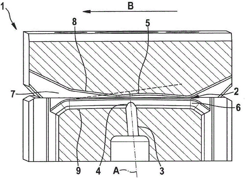
[0087] figure 1 A nozzle 1 according to the invention is shown in cross section with a yarn channel 2 and an air hole 3 . The yarn channel 2 is formed by interconnected plates 8 , 9 . The air hole 3 has a longitudinal axis A and merges into the yarn channel 2 in the merging opening 4 . In the yarn channel 2, the filaments 10 (not shown, see e.g. image 3 ) is conveyed along the conveying direction B. The merging inlet 4 is located approximately in the center of the nozzle 1 along the conveying direction B and is arranged at an angle of approximately 85° relative to the conveying direction B. Entanglement air 13 (not shown, see Figure 5 ) is introduced into the yarn channel 2 through the air holes 3 in the direction of the longitudinal axis A via the merging inlet 4 . The entangled air impinges on the baffle face 5 in a vertical manner. Due to the impact of the entangled air 13 on the baffle face 5, two local flow turbulences 13', 13" are formed (not shown, see Figure ...
PUM
 Abstract
Description
Claims
Application Information
 - Generate Ideas
- Intellectual Property
- Life Sciences
- Materials
- Tech Scout
- Unparalleled Data Quality
- Higher Quality Content
- 60% Fewer Hallucinations
Browse by: Latest US Patents, China's latest patents, Technical Efficacy Thesaurus, Application Domain, Technology Topic, Popular Technical Reports.
© 2025 PatSnap. All rights reserved.Legal|Privacy policy|Modern Slavery Act Transparency Statement|Sitemap|About US| Contact US: help@patsnap.com