
Plate cutting device

A cutting device and plate technology, applied in the field of plate processing, can solve the problems of low precision, unsuitable for mass production, low processing efficiency, etc., and achieve the effects of high processing precision, high-precision mass production, and improved production efficiency.

Inactive Publication Date: 2016-08-10
周玉翔
View PDF5 Cites 23 Cited by
  • Summary
  • Abstract
  • Description
  • Claims
  • Application Information

AI Technical Summary

Problems solved by technology

[0002] Most of the existing plate cutting devices are semi-automatic, requiring manual feeding, low processing efficiency, low precision, and not suitable for mass production. Therefore, we propose a plate cutting device

Method used


Image

  • Plate cutting device
  • Plate cutting device

Examples


Embodiment Construction

[0012] The following will clearly and completely describe the technical solutions in the embodiments of the present invention with reference to the accompanying drawings in the embodiments of the present invention. Obviously, the described embodiments are only some, not all, embodiments of the present invention. Based on the embodiments of the present invention, all other embodiments obtained by persons of ordinary skill in the art without making creative efforts belong to the protection scope of the present invention.

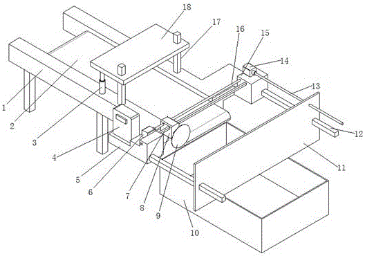
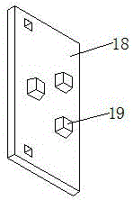
[0013] see Figure 1-2 , the present invention provides a technical solution: a plate cutting device, including a main support 1, a transmission device 2 is installed in the middle of the main support 1, an electric telescopic rod 3 is installed on both sides of the transmission device 2, and the upper end of the electric telescopic rod 3 is connected to the pressing plate 18 connections, the front side of electric telescopic rod 3 is equipped with guide rod t...


PUM


Abstract

The invention discloses a plate cutting device. The plate cutting device comprises a main support, a conveying device is arranged in the middle of the main support, electric telescopic rods are arranged on the two sides of the conveying device, the upper ends of the electric telescopic rods are connected with a pressing plate, and third guide rods are mounted on the front sides of the electric telescopic rods; through holes in sliding connection with the third guide rods are formed in the pressing plate, and a pressing block is arranged on the lower side face of the pressing plate; one end of the main support is connected with a first auxiliary support and a second auxiliary support, a first guide rod is arranged between the first auxiliary support and the second auxiliary support, and a cutting motor is in sliding connection to the first guide rod; and a blade is fixed to an output shaft of the cutting motor, a first stepping motor is mounted on the first auxiliary support, and an output shaft of the first stepping motor is connected with one end of a first lead screw through a coupler. The plate cutting device can achieve full-automatic production, an automatic compressing mechanism is adopted, the machining precision is high, and high-precision large-batch production can be achieved.

Description

technical field [0001] The invention relates to the technical field of plate processing, in particular to a plate cutting device. Background technique [0002] Most of the existing plate cutting devices are semi-automatic, requiring manual feeding, low processing efficiency, low precision, and not suitable for mass production. Therefore, we propose a plate cutting device. Contents of the invention [0003] The object of the present invention is to provide a steel plate cutting device to solve the problems raised in the background art above. [0004] In order to achieve the above object, the present invention provides the following technical solutions: a plate cutting device, including a main bracket, a transmission device is installed in the middle of the main bracket, and electric telescopic rods are installed on both sides of the transmission device. The upper end is connected with the pressure plate, the front side of the electric telescopic rod is equipped with a guid...

Claims


Application Information

Patent Timeline
Patent Type & Authority Applications(China)
IPC IPC(8): B23D19/00B23D33/02B23D33/10B26D1/16B26D7/01B26D7/00
CPCB23D19/00B23D33/02B23D33/10B26D1/16B26D7/00B26D7/015
Inventor 周玉翔
Owner 周玉翔
Learn More