Stroke regulation built-in precise fast press machine, and oil cylinder and use method thereof
A stroke adjustment, built-in technology, applied in the field of hydraulic presses, can solve the problems of complex structure of the adjustment mechanism, low production efficiency, high cost, etc., and achieve the effect of improving stability, reliability, accuracy, and preventing accidental loosening
- Summary
- Abstract
- Description
- Claims
- Application Information
AI Technical Summary
Problems solved by technology
Method used
Image
Examples
Embodiment 1
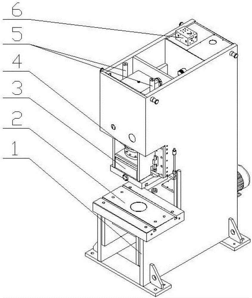
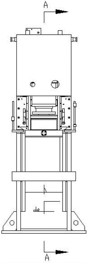
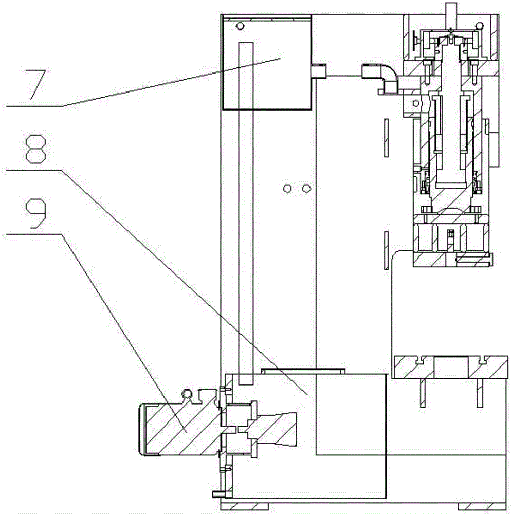
[0048] Such as figure 1 , figure 2 , image 3 As shown, a stroke adjustment built-in precision fast press includes a body 1, a workbench 2, a slider 3 and a hydraulic system. The hydraulic system includes a main cylinder 4, a fast cylinder 5, a hydraulic valve group 6, an upper oil tank 7, Lower oil tank 8 and oil pump motor 9, workbench 2, main oil cylinder 4, fast oil cylinder 5, hydraulic valve group 6, upper oil tank 7, lower oil tank 8 and oil pump motor 9 are all fixedly arranged on the fuselage 1, wherein the upper oil tank 7 is fixed It is arranged on the top of the fuselage 1, and the lower fuel tank 8 is fixedly arranged on the bottom of the fuselage 1;
[0049] Such as Figure 4 , Figure 5 and Figure 6 As shown, the master cylinder 4 includes a master cylinder piston rod 31 and a master cylinder body 32, the master cylinder body 32 is fixedly connected with the fuselage 1, the upper end of the master cylinder piston rod 31 extends into the master cylinder bo...
Embodiment 2
[0064] A method of using a built-in precision fast press with stroke adjustment, which is the same as that of Example 1, except that the upper and lower molds are checked in the mold adjustment step E. When the overlap of the upper and lower molds is 1.5mm, the following steps need to be continued First, control the master cylinder piston rod 31 to ascend L (L > 1.5mm), stop the oil pump motor 9; start the stroke adjustment motor again, drive the worm to rotate, and the worm drives the worm wheel 38 to rotate, the worm wheel 38, the limit nut 37 and the adjustment screw 33 Rotate as a whole relative to the main cylinder body 32, the adjusting screw 33 drives the adjusting nut 35 to rotate, and the encoder connected to the encoder connection seat 39 at the upper end of the adjusting screw 33 starts counting, and the adjustment nut 35 descends through PLC calculation and screen display Stop at 1 mm, and this step ends.
PUM
 Abstract
Description
Claims
Application Information
 - R&D
- Intellectual Property
- Life Sciences
- Materials
- Tech Scout
- Unparalleled Data Quality
- Higher Quality Content
- 60% Fewer Hallucinations
Browse by: Latest US Patents, China's latest patents, Technical Efficacy Thesaurus, Application Domain, Technology Topic, Popular Technical Reports.
© 2025 PatSnap. All rights reserved.Legal|Privacy policy|Modern Slavery Act Transparency Statement|Sitemap|About US| Contact US: help@patsnap.com


