Signal conditioning device and signal conditioning method for subarray-level digital T/R assembly based on transmitting-receiving separation

A signal conditioning and sub-array-level technology, applied in the field of testing, can solve problems such as poor scalability and maintainability, difficult engineering implementation, and large-scale switch network, so as to improve scalability and maintainability indicators and engineering implementation feasibility High and low difficulty in system integration

Active Publication Date: 2016-08-10
CHINA ELECTRONIS TECH INSTR CO LTD
View PDF3 Cites 6 Cited by
  • Summary
  • Abstract
  • Description
  • Claims
  • Application Information

AI Technical Summary

Problems solved by technology

[0010] (1) A large number of RF test components such as directional couplers or single-pole double-throw switches are required, which is not only costly, but also difficult to carry out system integration, and the engineering implementation is difficult;
[0011] (2) If the directional coupler is replaced with a single-pole double-throw switch, the test safety is low. Once the single-pole double-throw switch fails, the power divider is easily burned;
[0012] (3) The switch network adopts an integrated design idea, that is, a switch network is used to connect with the digital T / R component under test and the test instrument. The scale of the switch network is large, and the scalability and maintainability are poor;
[0013] (4) The noise figure needs to be serially tested one by one with the help of the emission test conditioning channel, and the test efficiency is relatively low

Method used


Image

  • Signal conditioning device and signal conditioning method for subarray-level digital T/R assembly based on transmitting-receiving separation
  • Signal conditioning device and signal conditioning method for subarray-level digital T/R assembly based on transmitting-receiving separation
  • Signal conditioning device and signal conditioning method for subarray-level digital T/R assembly based on transmitting-receiving separation

Examples


Embodiment Construction

[0032] The following will clearly and completely describe the technical solutions in the embodiments of the present invention with reference to the accompanying drawings in the embodiments of the present invention. Obviously, the described embodiments are only some, not all, embodiments of the present invention. Based on the embodiments of the present invention, all other embodiments obtained by persons of ordinary skill in the art without making creative efforts belong to the protection scope of the present invention.

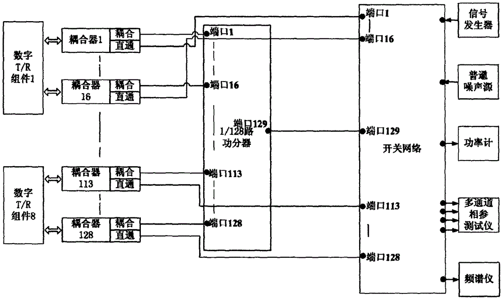
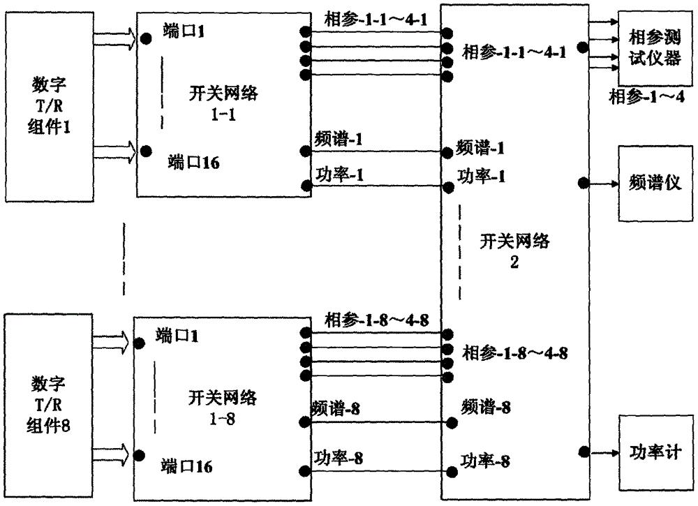
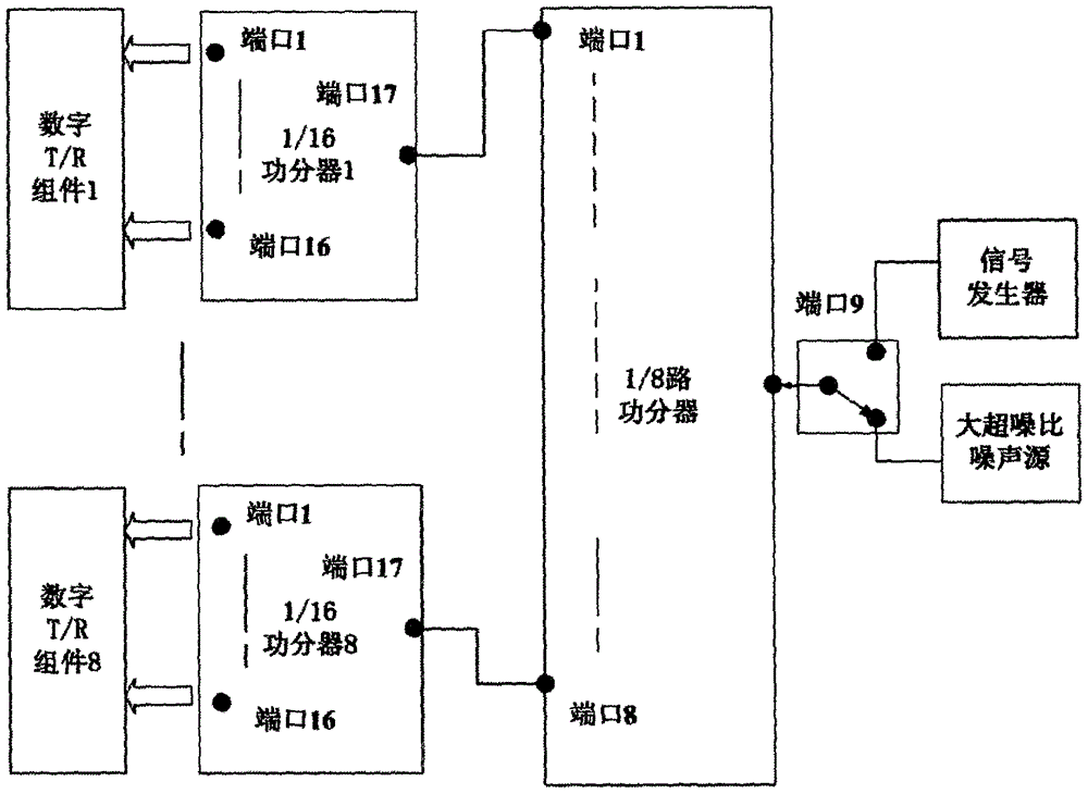
[0033] The current subarray-level digital T / R component test system signal conditioning scheme is derived from a single component test scheme, and has not paid attention to the difficulty of system integration after the test scale increases sharply. In addition, the switch network will be more complex and large, which also brings problems such as scalability and poor maintainability. If the solution of replacing the directional coupler with a single-pole doubl...


PUM


Abstract

The invention provides a signal conditioning device for a subarray-level digital T / R assembly based on transmitting-receiving separation. When a transmitting test is conducted, each digital T / R assembly is connected to a first-stage switching network, and construction of a test channel required by an assembly transmitting test is realized in the first-stage switching network; a second-stage switching network realizes distribution of test resources, the test resources in a system are switched to any one first-stage switching network through a switch, and a test for transmitting parameters is completed by using an instrument resource configured by the system after transmitting signal conditioning of the two-stage switching network; and when a receiving test is conducted, a switching network is not introduced any more, excitation signals outputted by a signal generator and calibration noises outputted by a noise source get into each digital T / R assembly through a single-pole double-throw switch and a two-stage power divider based on a hierarchical power division framework. According to the invention, a lot of microwave components are saved, the system integration difficulty is low, the engineering realization feasibility is high, and the cost is low.

Description

technical field [0001] The present invention relates to the technical field of testing, in particular to a sub-array-level digital T / R component signal conditioning device, and also to a sub-array-level digital T / R component signal conditioning method. Background technique [0002] Digital array radar is a fully digital phased array radar that adopts digital beamforming technology for both transmission and reception. Compared with traditional phased array radar, digital array radar has its incomparable advantages, such as large dynamic range, easy realization of multi-beam, low loss, low sidelobe, low angle measurement with high precision, strong manufacturability, and reliable system tasks Therefore, the application prospect of digital array radar is very broad. [0003] The digital T / R component is the most important and most numerous basic unit of the digital array radar. The digital T / R component is a microwave-digital mixed multi-channel radar transmitting / receiving mo...

Claims


Application Information

Patent Timeline
Patent Type & Authority Applications(China)
IPC IPC(8): G01S7/40
CPCG01S7/4004
Inventor 丁志钊吴家亮孙运臻刘忠林蒋玉峰季汉国段志强徐宝令
Owner CHINA ELECTRONIS TECH INSTR CO LTD
Why Eureka
Try Eureka