Improved type high-voltage current transformer

A high-voltage current and transformer technology, which is applied in the direction of inductors, transformers, transformer/inductance components, etc., can solve the problems of application and promotion restrictions, and achieve the effect of ensuring stability, reliability, firm strength, and high firmness

Inactive Publication Date: 2016-08-10
胡妍
View PDF5 Cites 4 Cited by
  • Summary
  • Abstract
  • Description
  • Claims
  • Application Information

AI Technical Summary

Problems solved by technology

Most of the existing zero-sequence current transformers are installed by means of flange installation or bonding. The installation location generally needs to be reserved, so its application and promotion are more restricted.

Method used


Image

  • Improved type high-voltage current transformer
  • Improved type high-voltage current transformer
  • Improved type high-voltage current transformer

Examples


Embodiment 1)

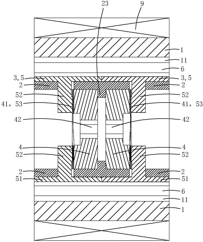
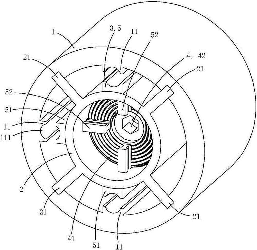
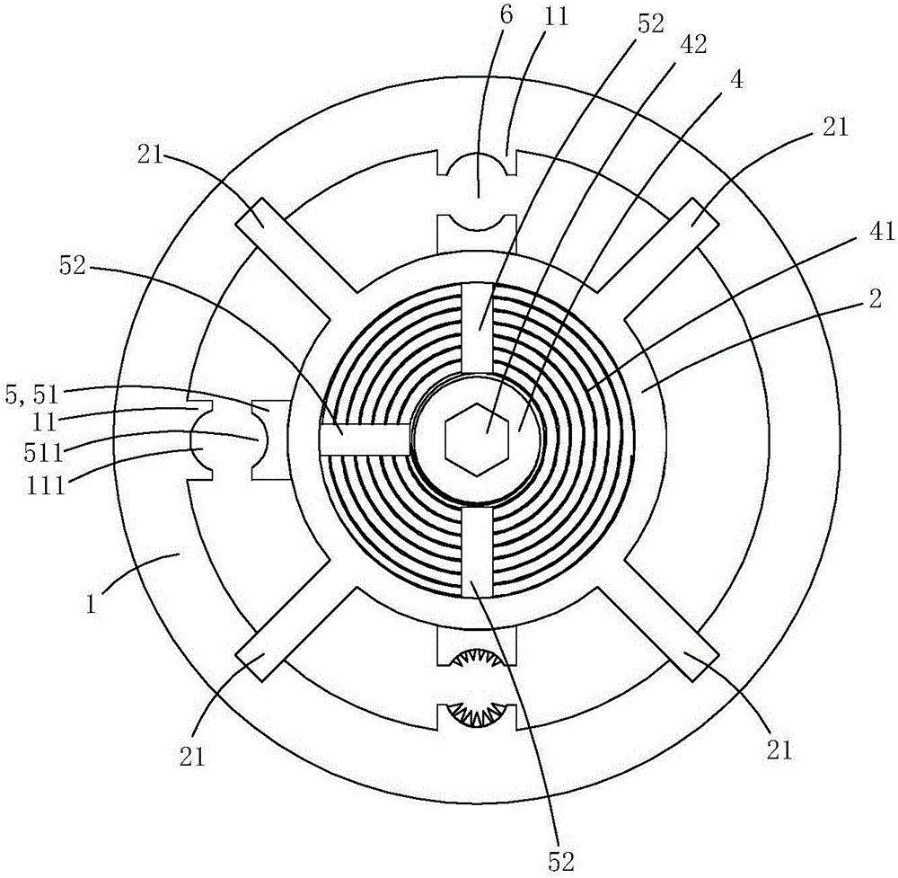
[0018] This embodiment is an improved high-voltage current transformer, see Figure 1 to Figure 6 As shown, it includes a base pipe 1 , a core pipe 2 , two sets of pressing jaw assemblies 3 , two flat nuts 4 and a current transformer 9 .

[0019] The inner peripheral wall of the base pipe is provided with three crimping bosses 11 along the axial direction of the base pipe, and the inner wall of each crimping boss is provided with an arc-shaped groove 111; the inner peripheral wall of the base pipe is also provided with four positioning slides along the axial direction of the substrate Slot 12; the core tube and the base tube are concentrically arranged and located in the base tube lumen; the outer peripheral wall of the core tube is provided with four supporting convex plates 21 protruding radially along the core tube, and the outer ends of each supporting convex plate are located at corresponding to a positioning chute, so that the core tube is supported and positioned in the...

Embodiment 2)

[0030] The base pipe 1 is provided with a mounting screw hole 15 radially penetrating through the wall of the base pipe; a temperature sensing device 8 is fixedly installed in the mounting screw hole.

[0031] The temperature sensing device 8 includes a metal housing 81 made of metal material with a containing groove 811, a temperature sensor 82 arranged in the containing groove, and a spring 83 for crimping the temperature sensor on the bottom wall of the containing groove , The screw pipe plug 84 that is used for limit spring.

[0032] One end 812 of the metal shell close to the central axis of the core tube is provided with a heat conduction boss 813 used as a puncture, and one end 814 of the metal shell away from the central axis of the core tube is provided with an inner hexagonal screw groove 815; There is an external thread 816 adapted to the mounting screw hole, and an internal thread area 817 is provided on the inner peripheral wall of the accommodating groove; the ...


PUM


Abstract

The invention discloses an improved type high-voltage current transformer. The current transformer comprises a base tube, a core tube, two sets of pressing claw assemblies, two planar nuts and a current transformer, wherein the current transformer is arranged on the base tube in a sleeving manner; the base tube is equipped with crimping bosses; radial limiting sliding holes are formed in the tube wall of the core tube; one or more blocking tables are arranged on the inner circumferential wall of the core tube; the two planar nuts are both rotationally arranged in the tube cavity of the core tube, and are arranged on the two sides of the corresponding blocking table respectively; the driving thread parts of each set of pressing claw assembly are positioned on one side, far from the corresponding blocking table, of the corresponding planar nut; each planar nut comprises a fastening part and a planar thread part which is meshed with and adapted to the driving thread part of each pressing claw of the corresponding one set of pressing claw assembly; and one or more mounting screw holes with one or more built-in temperature sensing apparatuses are formed in the base tube. The improved type high-voltage current transformer has an excellent anti-loosing effect.

Description

technical field [0001] The invention belongs to the technical field of electric power, and in particular relates to an improved high-voltage current transformer. Background technique [0002] The basic principle of zero-sequence current protection is based on Kirchhoff's current law: the algebraic sum of the complex current flowing into any node in the circuit is equal to zero. When the line and electrical equipment are normal, the vector sum of the currents of each phase is equal to zero. Therefore, the secondary side winding of the zero-sequence current transformer has no signal output, and the actuator does not operate. When an electric shock or leakage fault occurs, the vector sum of the currents of each phase is not zero, and the fault current causes magnetic flux in the iron core of the zero-sequence current transformer, and the current generated by the zero-sequence current transformer is the zero-sequence current. When the protection mechanism receives the zero-sequ...

Claims


Application Information

Patent Timeline
Patent Type & Authority Applications(China)
IPC IPC(8): H01F27/06H01F38/30H01F27/40H02G7/04F16L3/10G01K7/22
CPCH01F27/06F16L3/10G01K7/22H01F27/402H01F38/30H01F2027/406H02G7/04
Inventor 胡妍
Owner 胡妍
Why Eureka
Try Eureka