
Surface-mounted permanent magnet motor structure

A permanent magnet motor, surface-mounted technology, applied in the direction of magnetic circuit shape/style/structure, magnetic circuit, electrical components, etc., to achieve the effect of simple fastening method, convenient assembly and low price

Pending Publication Date: 2016-08-10
NANTONG JINCHI MECHANICAL ELECTRIC
View PDF0 Cites 7 Cited by
  • Summary
  • Abstract
  • Description
  • Claims
  • Application Information

AI Technical Summary

Problems solved by technology

At present, most of the permanent magnet motors manufactured in China have a built-in magnetic circuit structure. The structure is simple and the process implementation is relatively mature. Many domestic manufacturers are very experienced in manufacturing permanent magnet motors with built-in structures.

Method used


Image

  • Surface-mounted permanent magnet motor structure
  • Surface-mounted permanent magnet motor structure

Examples


Embodiment Construction

[0010] The technical scheme of the present invention is described in detail below in conjunction with accompanying drawing:

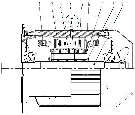
[0011] Such as figure 1 As shown, a surface-mounted permanent magnet motor structure, including a stator core 2 and a stator winding 1 connected to the stator core 2, is characterized in that a rotor core 5 is arranged between the stator core 2 and the shaft 9, and the rotor core 5 and the stator core The magnetic steel 3 and the latitude-free belt 4 are respectively arranged between the 2, and the rotor end plates 6 are respectively arranged on both lateral sides of the rotor core 5, and the self-cooling centrifugal blades 7 are arranged on the rotor end plates 6; the rotor core 5 is axially close to the shaft 9 Rotor tightening fasteners 8 are arranged on both sides.

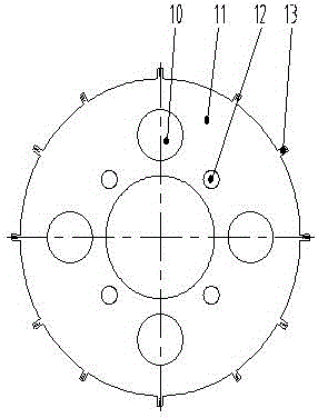
[0012] Such as figure 2 As shown, the rotor core 5 of the present invention is composed of several rotor punches 11, magnetic steel slots at an angle of 30° are evenly arranged on th...


PUM


Abstract

The invention discloses a surface-mounted permanent magnet motor structure, and belongs to the technical field of motor design. The surface-mounted magnetic steel design provided by the invention belongs to a partially embedded magnetic steel arrangement mode and has a great difference from a general magnetic steel arrangement mode in design emphasis. The structure comprises a stator iron core and a stator winding connected with the stator iron core. A rotor iron core is arranged between the stator iron core and a shaft. The magnetic steel and a welfless band are arranged between the rotor iron core and the stator iron core. Rotor end plates are arranged at two transverse sides of the rotor iron core. Self-cooling centrifugal fan blades are arranged on the rotor end plates. Two sides of the rotor iron core axially close to the shaft are equipped with rotor tensional fastening elements. The structure is simple in structure and low in cost and is suitable for mass production. According to the structure, the motor is ensured to have good speed regulation characteristic and operation reliability.

Description

technical field [0001] The invention belongs to the technical field of motor design. Among them, the design of the surface-mounted magnets of the present invention belongs to the layout of partially embedded magnets, which is also very different from the usual layout of magnets in terms of design focus. Background technique [0002] my country is a country rich in permanent magnet materials, especially rare earth permanent magnet material NdFeB resources are very rich in my country, and the reserves of rare earth ore are about 4 times the sum of other countries in the world. The scientific research level of rare earth permanent magnet materials and rare earth permanent magnet motors has reached the international advanced level. Therefore, for our country, the permanent magnet synchronous motor has a good application prospect. The permanent magnet synchronous motor has simple structure, small size, light weight, low loss, high power density, and high efficiency. Compared wi...

Claims


Application Information

Patent Timeline
Patent Type & Authority Applications(China)
IPC IPC(8): H02K1/27
CPCH02K1/278
Inventor 向翰
Owner NANTONG JINCHI MECHANICAL ELECTRIC
Learn More