Scanning range finder

A technology of optical distance measuring instrument and distance measuring circuit, which is applied in the direction of instruments, measuring devices, radio wave measuring systems, etc.

Active Publication Date: 2016-08-10
IROBOT CORP
View PDF9 Cites 13 Cited by
  • Summary
  • Abstract
  • Description
  • Claims
  • Application Information

AI Technical Summary

Problems solved by technology

Such measurements using the speed of light can be very fast, but may also require fast detector electronics for accurate measurements

Method used


Image

  • Scanning range finder
  • Scanning range finder
  • Scanning range finder

Examples


Embodiment Construction

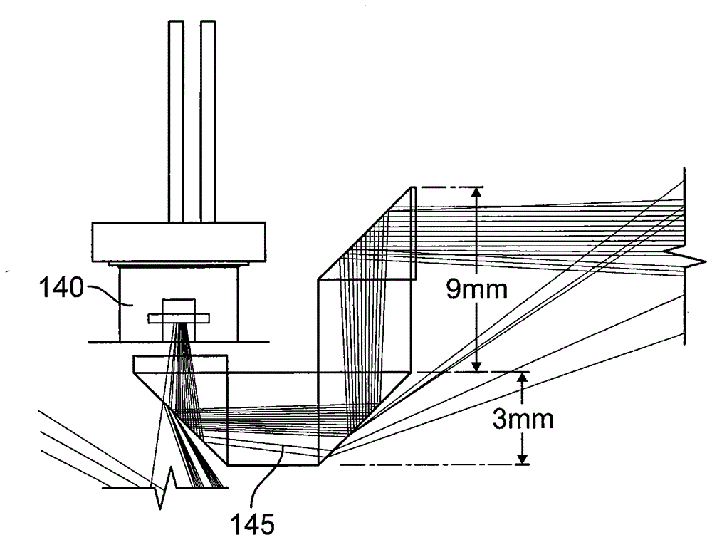
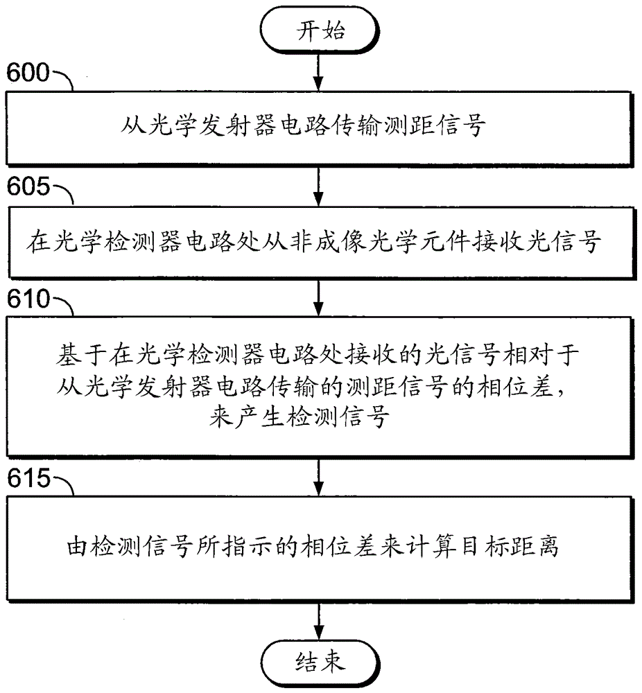
[0052] Autonomous robots that perform functions such as floor cleaning and lawn mowing rely on identifying obstacles, typically user-defined or invisible, to limit their movement. Such a robot can use a triangulation-based localization system to determine the robot's position within the perimeter. In the lawnmower example, signals sent between the lawnmower located in the garden property and beacons or environmental features around the lawn allow the lawnmower to calculate the robot's current position to estimate angles and distances. Systems and methods related to scanning rangefinders for use with robotic lawn mowers and other robotic devices are described herein. In some examples described herein, the scanning rangefinder includes non-imaging optics. In some additional embodiments, the systems and methods described herein recognize and account for wrap-back, which enables distances beyond wrap-back to appear as closer distances. Identifying and accounting for rollback ca...


PUM


Abstract

A scanning optical range finder in a mobile robot includes an optical emitter circuit, a non-imaging optical element, an optical detector circuit, and a ranging circuit. The non-imaging optical element is arranged to receive optical signals at an entrance aperture thereof responsive to operation of the optical emitter circuit, and to direct the optical signals to an output aperture thereof. The optical detector circuit is configured to receive the optical signals from the output aperture of the non-imaging optical element, and to generate detection signals based on respective phase differences of the optical signals relative to corresponding outputs of the optical emitter circuit. The ranging circuit is configured to calculate a range of a target from the phase differences indicated by the detection signals. Related devices and methods of operation are also discussed.

Description

[0001] priority claim [0002] This application claims the benefit of and priority to US Provisional Patent Application No. 61 / 899,045, filed November 1, 2013, entitled "SCANNING RANGE FINDER," the disclosure of which is incorporated herein by reference in its entirety. technical field [0003] The present disclosure relates to scanning optical range finders. In particular, systems and methods related to scanning optical rangefinders in mobile robots, such as lawn mowing robots and telepresence robots, are described herein. Background technique [0004] A laser rangefinder can measure the distance to an object based on the propagation speed of light output from a laser. Typical laser rangefinders operate on the principle of time-of-flight by sending a laser pulse in a narrow beam towards a target and measuring the time it takes for the pulse to reflect from the target and return to the transmitter. The propagation speed of light in the air is relatively unaffected by tempe...

Claims


Application Information

Patent Timeline
Patent Type & Authority Applications(China)
IPC IPC(8): G02B26/10G01S17/10
CPCG01S17/42G01S7/4816G01S7/4817G01S17/10G01S17/36G01S7/497A01D34/008Y10S901/47G01S17/06
Inventor T.皮尔斯J.米利肯M.维尔加
Owner IROBOT CORP
Why Eureka
Try Eureka