
Atomizing device capable of increasing atomization quantity

A technology of atomization device and atomization amount, which is applied to spray devices, liquid spray devices, etc., can solve the problems of decreased atomization efficiency, influence of atomization amount, and reduction of effective atomization range, so as to reduce energy consumption and improve atomization. Quantitative effect

Active Publication Date: 2016-08-17
MICRO BASE TECH CORP
View PDF7 Cites 4 Cited by
  • Summary
  • Abstract
  • Description
  • Claims
  • Application Information

AI Technical Summary

Problems solved by technology

Yet this traditional orifice sheet will cause following shortcoming because of being limited by its plane shape: 1, when vibration energy is transmitted, its transmission direction is transferred toward the center by the outer periphery of this orifice sheet, so vibration energy The generated stress will be excessively concentrated in the center, which will cause the nozzle hole to break and shorten the service life; 2. Since the vibration energy is concentrated in the center, the atomization area is only formed near the center of the nozzle hole, so it can There are not many effective nozzle holes, and the amount of atomization is naturally not good; 3. Moreover, because the spray area is excessively concentrated in the central area, the density of the atomized liquid molecules is excessively concentrated, and it is easy to make the droplets collide in the center area. Together and combined into large-sized droplets, resulting in a decrease in atomization efficiency
However, in order to achieve the best atomization performance, the orifice sheet of this kind must have sufficient depth in order to achieve the best atomization performance, and the radius of curvature will usually be increased to reduce the effective atomization range; To increase the effective atomization range, it is necessary to increase the processing radius of curvature, resulting in shallower processing depth and poorer atomization efficiency.
Furthermore, since the orifice plate is made of metal material, the material itself will be stretched after processing, but the longer the diameter of the hemispherical structure, the lower the structural tension, resulting in weakened input force and a weaker overall structure. also weakened
Furthermore, due to the design of the hemispherical surface structure of the prior art orifice sheet, most of the vibration wave energy will still be concentrated in the central area after being transmitted, so that only the micropores located in the central part can effectively move, while the peripheral area The micropores cannot be used effectively due to insufficient vibration energy, resulting in that the atomization area cannot reach the original design area, and it will also affect the amount of atomization during use.
However, such as U.S. Patent No. 6651650, the plurality of nozzle holes on the nozzle hole plate are arranged in a hexagonal shape, which is expected to increase the atomization efficiency, but the actual effect is different from the atomization efficiency of the general circular arrangement. Not much, completely unable to increase the amount of atomization during use
[0005] Most of the designs of the above-mentioned orifice plates are aimed at improving the atomization efficiency, and the effect is limited, and there is no mention of energy consumption. In view of this, the inventor proposed an atomization device that can increase the amount of atomization , not only can increase the instant atomization amount, but also further reduce the energy consumption during use

Method used


Image

  • Atomizing device capable of increasing atomization quantity
  • Atomizing device capable of increasing atomization quantity
  • Atomizing device capable of increasing atomization quantity

Examples


Embodiment Construction

[0037] In order to enable your review committee members to clearly understand the content of the present invention, only the following descriptions are used together with the drawings, please refer to them.

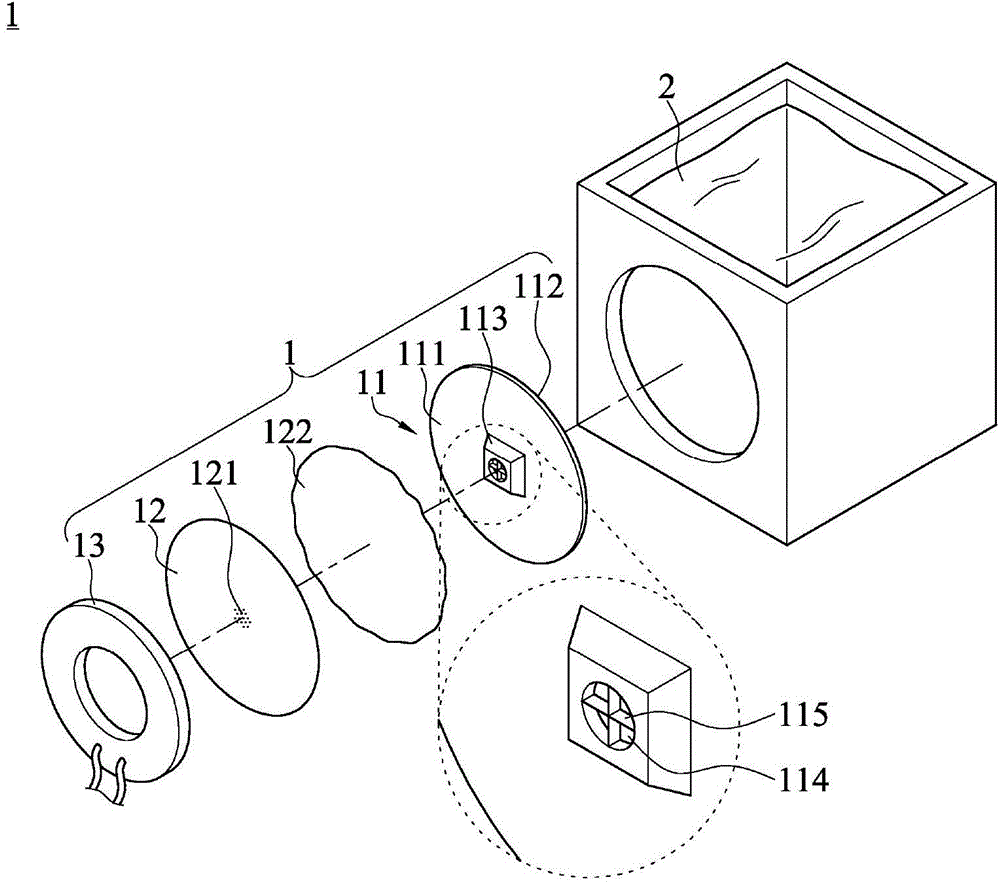
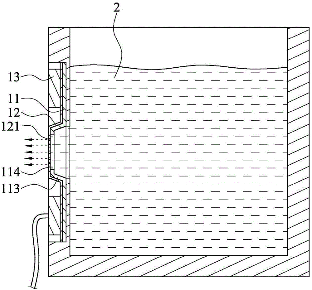
[0038] see figure 1 , figure 2 , is a three-dimensional exploded view and a combined sectional view of the first embodiment of the present invention. As shown in the figure, the atomization device 1 that can increase the atomization amount represented by the first embodiment of the present invention includes: a structural sheet 11 , an orifice sheet 12 and a piezoelectric ring 13 .

[0039] Wherein the structural sheet 11 is made of stainless steel sheet material, and it has a liquid outlet surface 111 and a liquid inlet surface 112, the structural sheet 11 is made to protrude toward the liquid outlet surface 111 by stamping technology to form a bulge 113, A perforation 114 is provided at the center of the raised portion 113, and the raised portion 113 is formed into a...


PUM


Abstract

The invention provides an atomizing device capable of increasing atomization quantity; the atomizing device comprises a structure sheet, a nozzle sheet and a piezoelectric ring; the punching technology is employed to form a through hole in the center of the structure sheet, and the surrounding of the through hole is provided with at least one stress gathering zone like a protrusion or deformation portion; the nozzle sheet is clamped between the structure sheet and the piezoelectric ring, and provided with a plurality of nozzles corresponding to the through hole; when the piezoelectric ring is driven to enable the structure sheet and the nozzle sheet to synchronically vibrate, a to-be-atomized liquid can be atomized and sprayed out from the plurality of nozzles close to the stress gathering zone, thus greatly improving instant atomization quantity, and further reducing application energy loss.

Description

technical field [0001] The present invention relates to the field of liquid atomization equipment, in particular to an atomization device that uses stamping technology to make a plurality of stress concentration points on a metal structure sheet, so that the amount of atomization can be greatly increased, and the energy consumption during use can be effectively reduced consumer. Background technique [0002] According to the current common liquid atomization device on the market, it uses a piezoelectric (PZT) ring made of piezoelectric materials such as lead zirconate titanate. When the voltage is input, the body and the attached metal back The plate produces a telescopic deformation phenomenon, which uses the vibration energy transmitted in the form of waves to make a nozzle hole sheet located on one side of the piezoelectric material, and the liquid near the nozzle hole is atomized into fine molecules and then sprayed out. [0003] The liquid atomizing device is mainly co...

Claims


Application Information

Patent Timeline
Patent Type & Authority Applications(China)
IPC IPC(8): B05B17/04
CPCB05B17/0646
Inventor 陈亿东林圣凯蔡定凯
Owner MICRO BASE TECH CORP
Learn More