System with double inner liquid spraying tool cathodes and electrolytic grinding and milling method of system with double inner liquid spraying tool cathodes

A tool cathode and electrolyte technology, which is applied to the double internal jet tool cathode system and the field of electrolytic milling, can solve the problem of prolonging the processing time, changing the error and poor machining allowance, and reducing the machining accuracy and machining efficiency of the electrolytic milling. and other problems, to achieve the effect of improving processing efficiency and processing accuracy, and increasing processing flexibility

Active Publication Date: 2016-08-17
NANJING UNIV OF AERONAUTICS & ASTRONAUTICS
8 Cites 6 Cited by

AI-Extracted Technical Summary

Problems solved by technology

Such a processing scheme requires repeated disassembly and clamping of the cathode of the grinding head, which is prone to reassembly errors and poor ...

Method used

(6), redundant electrolytic solution and electrolytic product in the working box 17 are filtered through filter 21...

Abstract

The invention relates to a system with double inner liquid spraying tool cathodes and an electrolytic grinding and milling method of the system with the double inner liquid spraying tool cathodes and belongs to the field of electrolytic grinding composite machining. A machine tool main shaft drives two hollow transmission shafts to rotate through a transmission straight gear set so that rotating connector inner rings at the top ends of the transmission shafts and water stopping chucks at the tail ends of the transmission shafts can be driven to rotate at the same time. The tool cathodes of different design requirements can be clamped on the water stopping chucks. Rotating connectors input electrolyte into a dynamic rotating system from a static system, and the electrolyte is directly jetted to a machined surface of a workpiece through transmission shaft through holes and tool cathode inner holes. In this way, complicated thin-wall structures, symmetrical molded faces and the like can be machined in an inner liquid spraying electrolytic grinding and milling manner through a main shaft transmission device, the machine tool main shaft is free of influences of electrolyte corrosion, the machining allowance difference is reduced, the machining depth is increased, and the machining precision, the machining efficiency and the machining flexibility are improved.

Technology Topic

Thin walledThrough transmission +7

Image

  • System with double inner liquid spraying tool cathodes and electrolytic grinding and milling method of system with double inner liquid spraying tool cathodes
  • System with double inner liquid spraying tool cathodes and electrolytic grinding and milling method of system with double inner liquid spraying tool cathodes
  • System with double inner liquid spraying tool cathodes and electrolytic grinding and milling method of system with double inner liquid spraying tool cathodes

Examples

  • Experimental program(1)

Example Embodiment

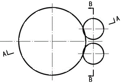
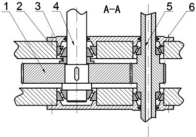
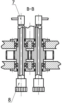
[0018] according to figure 1 , figure 2 with image 3 As shown, the main shaft transmission device for cathodic electrolytic milling with double internal spray tools is composed of the following parts: The electrolytic milling machine main shaft 4 drives two hollow drive shafts 5 to rotate simultaneously through the transmission spur gear set 1, and then the drive shaft 5 drives The rotary joint 6 at the top end and the water stop chuck 7 at the end rotate together. Both the machine tool 4 and the transmission shaft 5 are supported by two angular contact bearings 3. The spur gear set is externally meshed with two driven small spur gears of the same size through a driving large spur gear, and the two small spur gears are not in contact and are separated from each other. Distance, the gear is positioned by the shaft shoulder, the sleeve 2 and the key, and is installed according to the standard.
[0019] Combine below figure 1 , figure 2 , image 3 , Figure 4 with Figure 5 Explain the steps of using the main shaft transmission device proposed by the present invention to realize the cathodic electrolytic milling of a thin-walled structure with dual internal spray tools:
[0020] (1) First, clamp the two tool cathodes 19 on the water stop chucks 7 at the ends of the two drive shafts 5, and connect the negative pole of the power supply 24; then clamp the workpiece 20 on the workbench 18, and connect the power supply 24 positive; then complete tool setting and positioning under the control of the CNC motion program of the machine tool.
[0021] (2) Heat the electrolyte 25 to the required temperature through the temperature control unit 22, then turn on the centrifugal pump 16, the electrolyte 25 reaches the two branches through the three-way branch 15 and adjusts the pressure regulating valve 14 on each branch to The required working pressure can be displayed by the pressure gauge 12.
[0022] (3) Open the drain valve 13 on each branch, the electrolyte 25 with a certain pressure reaches the rotary joint 6 through the supply pipeline, and the electrolyte flow rate on each supply pipeline is dynamically monitored by the flow meter 11.
[0023] (4) The machine tool 4 is driven to rotate by the servo motor 9 of the electrolytic milling machine tool, and the speed of the machine tool 4 is adjusted by the frequency converter 8. In this way, the machine tool 4 drives the two hollow drive shafts 5 to rotate through the spur gear set 1 to further drive the drive shafts 5 The rotary joint 6 at the top end and the water stop chuck 7 at the end rotate, and the tool cathode 19 clamped on the water stop chuck 7 also rotates together.
[0024] (5) The electrolyte 25 can fill the entire processing area in time after spraying through the rotary joint 6, the through hole of the drive shaft 5, and the inner hole of the tool cathode 19. The worktable moves according to a predetermined trajectory under the control of the CNC motion program of the machine tool. The shape of both sides of the thin-walled structure can be processed and formed at one time.
[0025] (6) The excess electrolyte and electrolysis products in the working box 17 are filtered by the filter 21, and then flow into the electrolyte tank 23 to realize the filtration and recycling of the electrolyte 25.

PUM

no PUM

Description & Claims & Application Information

We can also present the details of the Description, Claims and Application information to help users get a comprehensive understanding of the technical details of the patent, such as background art, summary of invention, brief description of drawings, description of embodiments, and other original content. On the other hand, users can also determine the specific scope of protection of the technology through the list of claims; as well as understand the changes in the life cycle of the technology with the presentation of the patent timeline. Login to view more.

Similar technology patents

Pump workpiece eccentricity circle machining tooling and use method thereof

ActiveCN106736778AImprove machining accuracy and machining efficiencyImprove equipment utilization
Owner:山东力嘉轻量化科技有限公司

Vehicle clamp capable of fast replacing machined part

InactiveCN104028794Alow costImprove machining accuracy and machining efficiency
Owner:SHAANXI FAST GEAR CO

Integrated two-station earing machine for tin plate earing rate detection sample processing

InactiveCN106311880AImprove machining accuracy and machining efficiencyGuaranteed detection accuracy
Owner:SHANGHAI BAOSTEEL IND TECHNOLOGICAL SERVICE

Processing method of needle plate insertion sheet

ActiveCN109112710AReduce processing difficultyImprove machining accuracy and machining efficiency
Owner:NINGBO CIXING

Tenon-and-mortise structure machining device and machining method

ActiveCN113601644AImprove machining accuracy and machining efficiency
Owner:HUBEI UNIV OF TECH

Classification and recommendation of technical efficacy words

  • Improve machining accuracy and machining efficiency

Dimension compensation quantity determining method for bearing machining

InactiveCN108262667AAvoid errorsImprove machining accuracy and machining efficiency
Owner:WAFANGDIAN BEARING GRP STATE BEARING ENG TECH RES CENT CO LTD

Catenary cantilever machining device

ActiveCN108583371ARealize fully automatic processingImprove machining accuracy and machining efficiency
Owner:CHINA CREC RAILWAY ELECTRIFICATION BUREAU GRP

End surface grooving device

ActiveCN104551016AReduce investment in fixed assetsImprove machining accuracy and machining efficiency
Owner:龙口市蓝牙数控装备有限公司

Slow cutter servo cutter path and design method thereof

ActiveCN111880472AEasy to calculateImprove machining accuracy and machining efficiency
Owner:SUZHOU UNIV OF SCI & TECH

Erected-inverted machine tool with double spindles and double knife towers

PendingCN111761079AImprove machining accuracy and machining efficiencyhigh degree of automation
Owner:湖北山铁智能装备有限公司
Why Eureka
Try Eureka