Electric heating rod assembly machine

A technology of electric heating and assembly mechanism, which is applied in the direction of assembly machines, metal processing, metal processing equipment, etc., and can solve the problems of increased labor costs, unqualified assembly of electric heating rods, and high accident rate

Active Publication Date: 2016-08-17
南通江海港建设工程有限公司
View PDF5 Cites 35 Cited by
  • Summary
  • Abstract
  • Description
  • Claims
  • Application Information

AI Technical Summary

Problems solved by technology

[0002] Electric heating rods are widely used in daily life. Electric heating rods are products specially designed and manufactured for electric heat tracing and heat preservation of containers such as storage tanks. Tank heaters have problems such as high accident rate, difficult maintenance, high energy consumption, etc. The problem of heat tracing and heat preservation has always troubled the majority of users. The electric heating rod is developed for these problems. The installation of the electric heating rod is complicated and increases labor costs. , will be subjected to different external forces during the assembly process, which will easily lead to unqualified electric heating rod assembly. In view of this, it is necessary to improve the existing electric heating rod assembly machine

Method used


Image

  • Electric heating rod assembly machine
  • Electric heating rod assembly machine
  • Electric heating rod assembly machine

Examples


Embodiment Construction

[0046] The preferred embodiments of the present invention will be described in detail below in conjunction with the accompanying drawings, so that the advantages and features of the invention can be more easily understood by those skilled in the art, so as to define the protection scope of the present invention more clearly.

[0047] see Figure 1 to Figure 34 , the embodiment of the present invention includes:

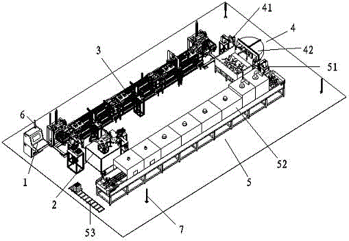
[0048] An electric heating rod assembly machine, the electric heating rod assembly machine includes an electric control box 1, a rotating assembly mechanism 2, a chain assembly line 3, a paint mechanism 4, a drying mechanism 5, an indicator light tower 6 and an area safety grating 7, the A light tower 6 is installed on the top plate of the electric control box 1, and a rotating assembly mechanism 2 is provided on the front side of the electric control box 1, and the rotating assembly mechanism 2 transports the first assembled workpiece to the chain assembly line 3 on ...


PUM


Abstract

The invention discloses an electric heating rod assembly machine. The electric heating rod assembly machine comprises an electric control box, a rotary assembly mechanism, a chain assembly line, a coating mechanism, a drying mechanism, an indicator lamp tower and area safety gratings, wherein the indicator lamp tower is mounted on the top plate of the electric control box; the front side of the electric control box is provided with the rotary assembly mechanism; the rotary assembly mechanism is used for conveying a workpiece assembled for a first time to the chain assembly line at the rear side of the rotary assembly mechanism; the chain assembly line is used for conveying a wokpiece assembled for a second time to the coating mechanism at the front right side of the chain assembly line; the coating mechanism is used for conveying an assembled electric heating rod to the drying mechanism at the front side of the coating mechanism; and the area safety gratings are arranged around in a rectangular manner. In this way, the assembly welding efficiency is high, the production stability is good, the product scrap rate is low, and the overall production efficiency is high.

Description

technical field [0001] The invention relates to the field of mechanical automation, in particular to an electric heating rod assembly machine. Background technique [0002] Electric heating rods are widely used in daily life. Electric heating rods are products specially designed and manufactured for electric heat tracing and heat preservation of containers such as storage tanks. Tank heaters have problems such as high accident rate, difficult maintenance, high energy consumption, etc. The problem of heat tracing and heat preservation has always troubled the majority of users. The electric heating rod is developed for these problems. The installation of the electric heating rod is complicated and increases labor costs. , will be subjected to different external forces during the assembly process, which will easily lead to unqualified assembly of the electric heating rod. In view of this, it is necessary to improve the existing electric heating rod assembly machine. Contents ...

Claims


Application Information

Patent Timeline
Patent Type & Authority Applications(China)
IPC IPC(8): B23P23/06B23P19/00B23P21/00B23P19/08
CPCB23P19/001B23P19/007B23P19/08B23P21/006B23P23/06
Inventor 刘俊
Owner 南通江海港建设工程有限公司
Why Eureka
Try Eureka