Spill hole retainer assembly for bathroom sanitary apparatuses and bathroom sanitary apparatus

A technology for overflow holes and equipment, which is applied in the field of sanitary equipment, can solve problems such as not being suitable for consumers to replace baffles by themselves, high processing precision requirements, and affecting decorative aesthetics, etc., to achieve stable connection, improve decorative aesthetics, The effect of easy disassembly and assembly

Active Publication Date: 2016-08-17
TAIZHOU OMSA SANITARY WARES CO LTD
View PDF5 Cites 1 Cited by
  • Summary
  • Abstract
  • Description
  • Claims
  • Application Information

AI Technical Summary

Problems solved by technology

Such as the baffle structure of the overflow hole of the bathroom equipment recorded in the Chinese patent literature (authorized announcement number CN204282464U), the baffle is detachably installed on the bathroom equipment; although the baffle structure has the advantages of being installed in the final process and a replaceable baffle, However, there are also the following deficiencies: 1. The expansion clamp must be screwed to a suitable posi

Method used


Image

  • Spill hole retainer assembly for bathroom sanitary apparatuses and bathroom sanitary apparatus
  • Spill hole retainer assembly for bathroom sanitary apparatuses and bathroom sanitary apparatus
  • Spill hole retainer assembly for bathroom sanitary apparatuses and bathroom sanitary apparatus

Examples


Embodiment 1

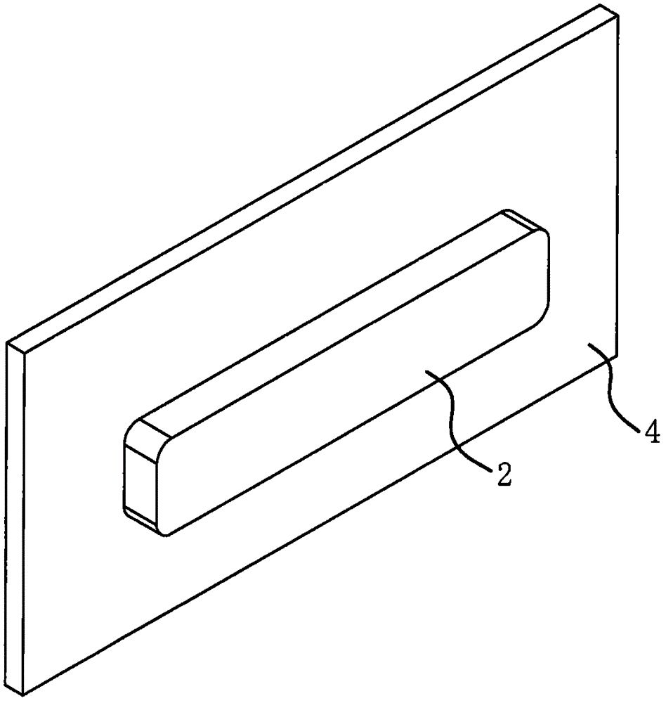
[0031] like Figure 3 to Figure 8 As shown, the overflow hole baffle assembly of the sanitary equipment includes a mounting base 1 and a baffle 2 . The blocking plate 2 is in the shape of a strip plate.

[0032] Mounting seat 1 is a basic component, and the number of mounting seat 1 is one; The mounting base 1 is compatible with the blocking plate 2, and the length and width of the mounting base 1 are smaller than the length and width of the blocking plate 2. Both ends of the mounting base 1 are provided with strip-shaped connecting grooves 1b, and two strip-shaped connecting grooves 1b are arranged perpendicularly to each other.

[0033] A mounting groove 2a is formed on the back of the blocking piece 2, and the mounting groove 2a is strip-shaped. A water inlet 2b communicating with the installation groove 2a is opened on the lower side of the blocking piece 2; the water inlet 2b is also strip-shaped. A hanging groove 2c extending longitudinally along the installation gro...

Embodiment 2

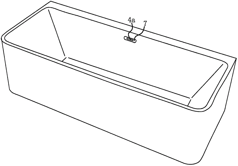
[0040] The structure and principle of this embodiment are basically the same as that of Embodiment 1, and the basic similarities will not be redundantly described, and only the differences will be described, and the differences are as follows: Figure 9 and Figure 10 As shown, the water inlet 2b on the baffle 2 is located on the front surface of the baffle 2 .

Embodiment 3

[0042] The structure and principle of this embodiment are basically the same as that of Embodiment 1, and the basic similarities will not be redundantly described, and only the differences will be described, and the differences are as follows: Figure 11As shown, the number of mounting bases 1 is two. The mounting base 1 is block-shaped, and the accompanying drawings in the manual Figure 11 It is given that the cross section of the mounting seat 1 is a regular hexagon; according to actual conditions, the cross section of the mounting seat 1 may also be a regular quadrilateral.

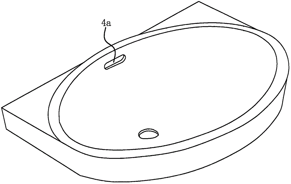
[0043] There is only one bar-shaped connecting groove 1b on each mounting base 1; the two mounting bases 1 are respectively located at both ends of the overflow hole 4a, that is, the corrugated parts 1a on the two mounting bases 1 are respectively embedded in the two ends of the hanging groove 2c Ministry.


PUM


Abstract

The invention provides a spill hole retainer assembly for bathroom sanitary apparatuses and a bathroom sanitary apparatus, belongs to the technical field of bathroom sanitary apparatuses and solves the problem that an existing retainer structure is unsuitable for most consumers to change on their own. The spill hole retainer assembly for the bathroom sanitary apparatus comprises a mount and a retainer, one surface of the retainer is provided with a mounting cavity, the retainer has a water inlet communicated with the mounting cavity, and one side of the mounting cavity is provided with a hanging notch; the mount is positioned in the mounting cavity and has a hanging edge portion insertable into the hanging notch; the other side of the mounting cavity is provided with a through screw hole corresponding to the hanging notch in position, a bolt is in threaded connection in the screw hole, and an end of the bolt is abuttable to the mount. The retainer in the spill hole retainer assembly for the bathroom sanitary apparatus is easy to demount and mount, and requirements of consumers for changing the retainer on their own are met.

Description

technical field [0001] The invention belongs to the technical field of sanitary equipment, and relates to a drainage structure of sanitary equipment, in particular to an overflow hole stop plate assembly for overflow holes of sanitary equipment. [0002] The invention belongs to the technical field of sanitary equipment, in particular to a sanitary equipment. Background technique [0003] The overflow hole refers to the water outlet hole at a specific height in the water container; figure 1 overflow hole as shown in the basin; figure 2 Overflow hole shown in bathtub. The overflow hole communicates with the drain hole, and when the water reaches the height of the overflow hole, the water will flow out from the overflow hole to prevent other losses caused by overflowing water. [0004] According to the actual situation, people can not decorate the overflow hole, and can also use decorative parts or baffles to decorate. like figure 1 As shown, there is no trim and blank i...

Claims


Application Information

Patent Timeline
IPC IPC(8): E03C1/244
CPCE03C1/244
Inventor 吴建国
Owner TAIZHOU OMSA SANITARY WARES CO LTD
Why Eureka
Try Eureka