Composite anchor rod device and method for fastening cross section by using anchor rod device in anchoring manner

A composite and anchor technology, which is applied in building maintenance, construction, building construction, etc., can solve the problems of insufficient concrete, reduce the bonding strength of new and old interfaces, and cumbersome construction procedures, so as to achieve high utilization rate and avoid interface Stripping, making simple and efficient effects

Inactive Publication Date: 2016-08-17
ZHEJIANG UNIV
View PDF11 Cites 2 Cited by
  • Summary
  • Abstract
  • Description
  • Claims
  • Application Information

AI Technical Summary

Problems solved by technology

At present, concrete cracks are mainly filled by injecting epoxy resin into the concrete through implantation holes under high pressure. However, this method is too cumbersome to use in the method of enlarging the cross-section reinforcement method, and it is easy to cause reinforcement after injecting the resin slurry and then spraying the concrete. The concrete at the reinforcement position is not full and there are certain gaps, which reduces the bond strength between the old and new interfaces

Method used


Image

  • Composite anchor rod device and method for fastening cross section by using anchor rod device in anchoring manner
  • Composite anchor rod device and method for fastening cross section by using anchor rod device in anchoring manner
  • Composite anchor rod device and method for fastening cross section by using anchor rod device in anchoring manner

Examples


Embodiment Construction

[0053] As shown in the drawings, the composite bolt device of the present invention includes a bolt 1, a positioning nut 2, a fixing cone 3, a fixing sleeve 4, a pressure plate 5 and a fastening nut 6;

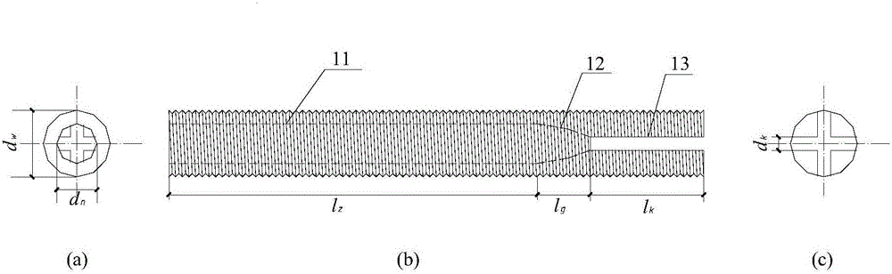
[0054] Anchor rod 1 is a threaded pipe with outer diameter d w The insertion end of the anchor rod 1 is provided with a separation groove communicating with the threaded hole. The anchor rod 1 is axially divided into a hollow section 11, a transition section 12 and a slotted section 13 with separation grooves. The length l of the hollow section 11 z 30mm, aperture d n is 6mm. The length l of the transition section 12 g is 4 mm, and the inner diameter of the transition section 12 gradually converges in the axial direction. The slotted section 13 has a separation groove, which is an axially extending cross groove, and is used to divide the rod body of the anchor rod 1 into several deformed parts that are extruded and expanded outward. The length of the cross groove is l k 10...


PUM


Abstract

The invention relates to a composite anchor rod device and a method for fastening a cross section by using the anchor rod device in an anchoring manner. The composite anchor rod device comprises an anchor rod, a positioning screw nut, a fixing cone, a fixing sleeve, a pressing plate and a fastening screw nut, wherein an inner threaded hole is formed inside the anchor rod; a partitioning groove which is communicated with the threaded hole is formed in an inserting end of the anchor rod; the partitioning groove is used for dividing a rod body into a plurality of deformation parts which are expanded outwards under the action of extrusion; the positioning screw nut is arranged on the anchor rod in a sleeving manner and is used for adjusting the insertion depth of the anchor rod; the fixing cone is inserted into the anchor rod, a sharp part has a conical surface for extruding the deformation part, and outer threads are fixed at a rear part; and one end of the fixing sleeve is connected with the fixing cone in a sleeving manner, and the pressing plate and the fastening screw nut for fixing the pressing plate are arranged at the other end of the fixing sleeve in a sleeving manner. By adopting the composite anchor rod device, the insertion depth of the anchor rod can be effectively controlled, on one hand, a part to be fastened can be prevented from a phenomenon that a concrete protecting layer is peeled and damaged, and on the other hand, a reinforced layer and the part to be fastened can be prevented from a damage phenomenon of interface peeling. The invention further discloses a method for fastening the cross section by using the anchor rod device in the anchoring manner.

Description

technical field [0001] The invention relates to the field of mechanical devices, in particular to a compound anchor device and a method for reinforcing a section by using the anchor device for anchoring. Background technique [0002] The enlarged section reinforcement method is often referred to as the enlarged section reinforcement method. It achieves the purpose of improving the bearing capacity, stiffness and stability of the component by using the same or better material as the original component, pouring concrete on the outside of the original component and adding enough steel bars to increase the cross-sectional size of the component. At present, the enlarging cross-section reinforcement method faces the same problems as other reinforcement methods, such as the peeling of the new and old interfaces and the peeling of the concrete protective layer. [0003] By setting a certain number of anchor bolts, the interface peeling can be effectively prevented, and when the anc...

Claims


Application Information

Patent Timeline
Patent Type & Authority Applications(China)
IPC IPC(8): E04G23/02
CPCE04G23/0218
Inventor 张大伟金伟良许晨施海锋李忠练其安
Owner ZHEJIANG UNIV
Why Eureka
Try Eureka