
Quasi-zero stiffness vibration isolator applicable to isolation of micro-amplitude and low-frequency vibration and realization method of quasi-zero stiffness vibration isolator

A low-frequency vibration, quasi-zero stiffness technology, applied in the direction of shock absorbers, spring/shock absorber functional characteristics, shock absorbers, etc., can solve the problems of small spring deformation and ineffective performance, and achieve increased deformation, Ease of processing and manufacturing, and the effect of improving performance

Inactive Publication Date: 2016-08-17
FUZHOU UNIV
View PDF5 Cites 24 Cited by
  • Summary
  • Abstract
  • Description
  • Claims
  • Application Information

AI Technical Summary

Problems solved by technology

The reason for the preliminary analysis of the researchers is that under the slight vibration, the deformation of the spring is very small, the negative stiffness mechanism is rarely involved, and basically does not work, resulting in the effect of canceling the positive and negative stiffness.

Method used


Image

  • Quasi-zero stiffness vibration isolator applicable to isolation of micro-amplitude and low-frequency vibration and realization method of quasi-zero stiffness vibration isolator
  • Quasi-zero stiffness vibration isolator applicable to isolation of micro-amplitude and low-frequency vibration and realization method of quasi-zero stiffness vibration isolator
  • Quasi-zero stiffness vibration isolator applicable to isolation of micro-amplitude and low-frequency vibration and realization method of quasi-zero stiffness vibration isolator

Examples


Embodiment Construction

[0020] In order to make the above-mentioned features and advantages of the present invention more comprehensible, the following specific embodiments are described in detail with reference to the accompanying drawings, but the present invention is not limited thereto.

[0021] refer to Figure 1 to Figure 5

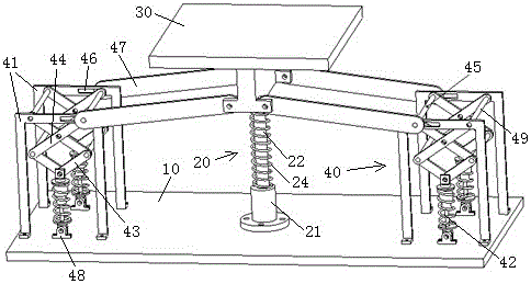
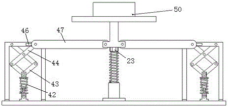
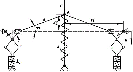
[0022] A quasi-zero-stiffness vibration isolator suitable for isolating micro-amplitude low-frequency vibrations includes a base 10, an elastic lifting mechanism 20 is arranged in the middle of the base, and an object stage 30 is arranged on the upper end of the elastic lifting mechanism. Both sides of the stage are respectively connected with negative stiffness mechanisms 40 arranged on both sides of the base.

[0023] In this embodiment, the elastic lifting mechanism includes a bearing seat 21 arranged in the middle of the base, and a guide rod 22 that can move up and down in the bearing seat is longitudinally pierced on the bearing seat, and the upper end of the guide ...


PUM


Abstract

The invention relates to a quasi-zero stiffness vibration isolator applicable to isolation of micro-amplitude and low-frequency vibration and a realization method of the quasi-zero stiffness vibration isolator and relates to the field of an isolation vibration device. The quasi-zero stiffness vibration isolator comprises a base, wherein an elastic hoisting mechanism is arranged in the middle of the base; an object carrying platform is arranged at the upper end of the elastic hoisting mechanism; and the two sides of the object carrying platform are connected with negative rigidity mechanisms arranged at the two side parts of the base respectively. The realization method comprises the steps: an object subjected to vibration isolation and having a certain weight is put on the object carrying platform to compress a spring; the object carrying platform moves downwards and drives a connecting rod; the connecting rod pushes a shaft rod to slide horizontally in a transverse groove of a fixed frame; a shearing and forking mechanism extends downwards and a resetting spring is compressed; the connecting rod moves on a horizontal position so that the vibration isolator is located at a balanced position; when external vibration and excitation act on the base, the vibration is transmitted onto the vibration isolator; and then the vibration isolator starts to work to isolate the micro-amplitude and low-frequency vibration. The vibration isolator provided by the invention not only can guarantee certain bearing capability and extremely low rigidity, but also has a stroke amplification effect; and meanwhile, the realization method is simple and convenient.

Description

technical field [0001] The invention relates to a quasi-zero-stiffness vibration isolator suitable for isolating micro-amplitude low-frequency vibrations and a realization method thereof, and relates to the field of vibration isolation devices. Background technique [0002] With the continuous development of modern science and technology, the status of vibration isolation technology in industrial production and engineering projects is becoming more and more important, especially for the isolation of low frequency and ultra-low frequency. Due to the limitations of linear vibration isolation systems, the application of nonlinear vibration isolation systems to low-frequency vibration isolation has become a research hotspot. In recent years, the quasi-zero stiffness vibration isolator composed of elements or mechanisms with negative stiffness characteristics connected in parallel with positive stiffness springs has been favored by many scholars. The quasi-zero stiffness system ...

Claims


Application Information

Patent Timeline
IPC IPC(8): F16F7/00
CPCF16F7/00F16F2228/063
Inventor 杨晓翔蓝双
Owner FUZHOU UNIV
Learn More