
Self-lubricating harmonic reducer

A harmonic reducer, automatic lubrication technology, applied in the direction of gear lubrication/cooling, transmission, transmission parts, etc., can solve problems such as increasing gear friction and reducing gear life.

Active Publication Date: 2016-08-17
铂睿(山东)精密工业有限公司
View PDF7 Cites 23 Cited by
  • Summary
  • Abstract
  • Description
  • Claims
  • Application Information

AI Technical Summary

Problems solved by technology

With this structure, the lubricant path is isolated into two oil paths, the gear lubricating part and the wave generator part, and the path from the lubricant supply in the flexspline cavity to the gear is blocked. Once the lubricant in the gear space is used up, It will increase the friction of the gear and reduce the life of the gear

Method used


Image

  • Self-lubricating harmonic reducer
  • Self-lubricating harmonic reducer
  • Self-lubricating harmonic reducer

Examples


Embodiment Construction

[0020] The present application will be further described in detail below with reference to the accompanying drawings and embodiments. It should be understood that the specific embodiments described herein are only used to explain the related invention, but not to limit the invention. In addition, it should be noted that, for the convenience of description, only the parts related to the invention are shown in the drawings.

[0021] It should be noted that the embodiments in the present application and the features of the embodiments may be combined with each other in the case of no conflict. The present application will be described in detail below with reference to the accompanying drawings and in conjunction with the embodiments.

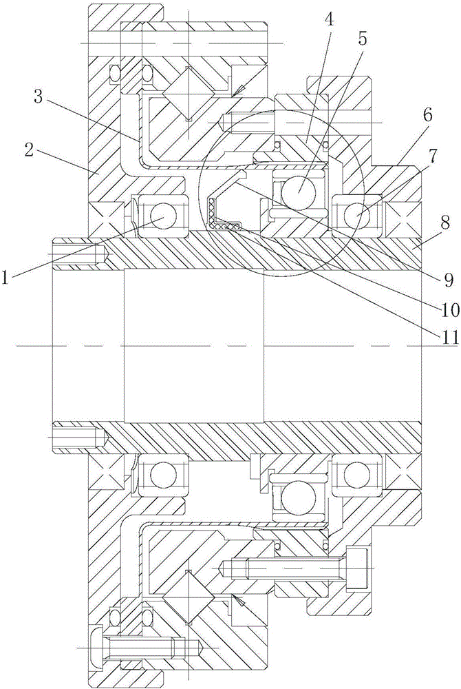
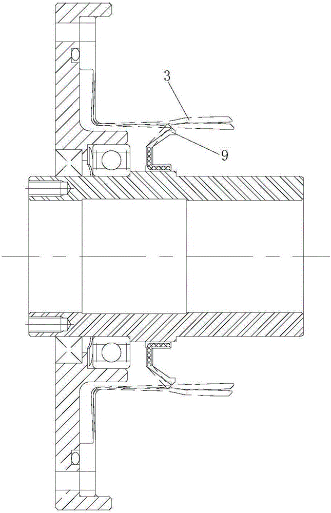
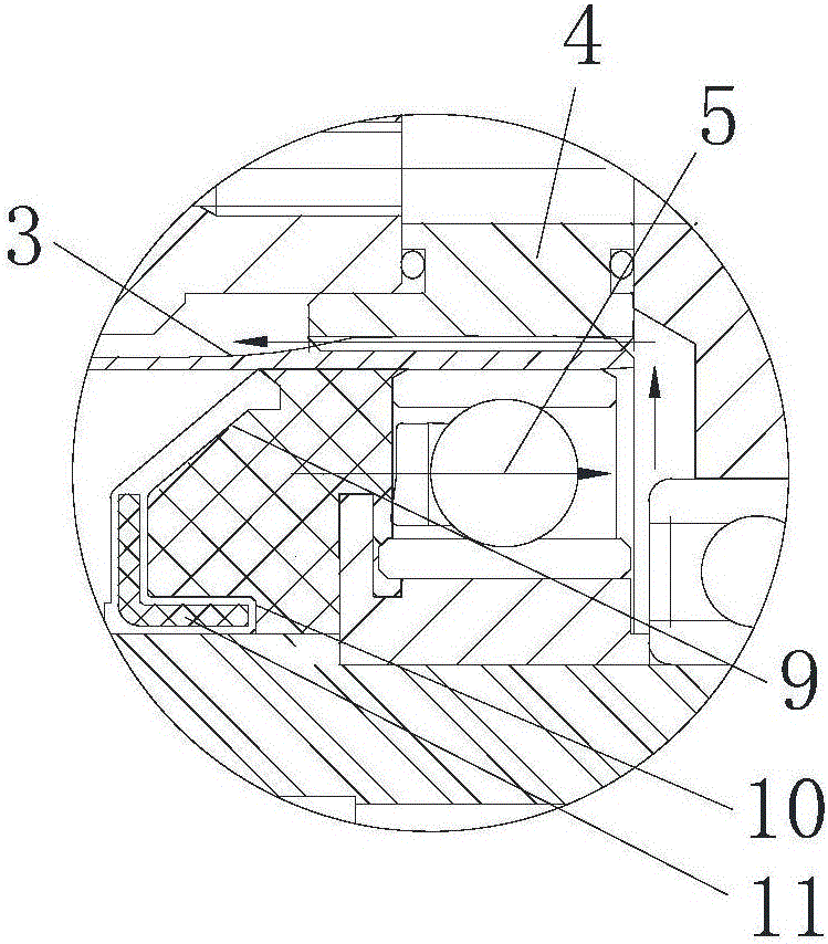
[0022] Please refer to figure 1 As mentioned above, the self-lubricating harmonic reducer provided by the embodiment of the present invention includes a wave generator 5, a rigid wheel 4 and a flexible pulley 3, the rigid pulley 4 is meshed with...


PUM


Abstract

The invention discloses a self-lubricating harmonic reducer. The self-lubricating harmonic reducer comprises a wave generator, a rigid gear and a flexible gear, wherein the rigid gear is meshed with the flexible gear; the wave generator is in contact with the inner wall of the flexible gear; an oil seal is arranged on an input shaft of the wave generator or an output end of the reducer in a sealing manner; a lubricant cavity is formed among the oil sea, the wave generator and the flexible gear; the oil seal comprises a ring-shaped base part; an elastic lip edge overhangs outwards from the outer side wall of the base part; the elastic lip edge is slantly arranged toward the wave generator; the overhanging tail end of the elastic lip edge tightly presses against the inner wall of the flexible gear. According to the reducer disclosed in the invention, the lubricant cavity, rather than the whole cavity in the flexible gear, is filled with the lubricant, so that the weight of the lubricant is decreased; the lubricating supply for the rigid gear and the flexible gear can be completed, and the flowing direction of the lubricant is not influenced by the mounting direction of the harmonic reducer, so that the favorable lubrication for the rigid gear and the flexible gear is ensured, the torn-up scrap iron of the rigid gear and the flexible gear is prevented from flowing back to the flexible bearing along with the lubricant, and the service life of the reducer is prolonged.

Description

technical field [0001] The present application generally relates to the technical field of harmonic reducers, and in particular, to an automatic lubricating harmonic reducer. Background technique [0002] Harmonic reducers are widely used in electronics, aerospace and aviation due to their high bearing capacity, large transmission ratio, small size, light weight, high transmission efficiency, long life, smooth transmission, no impact, no noise, and high motion accuracy. , Robotics and other industries. For example, the harmonic reducer is used in the transmission device of the robot. During the use of the robot, it will face various posture requirements. However, the lubricant is affected by gravity. When the use posture is that the wave generator is facing upward, the lubricant It is difficult to supply from the flex wheel gear cavity to the rigid wheel and the flex wheel, which causes insufficient lubrication between the rigid wheel and the flex wheel, increases the frict...

Claims


Application Information

Patent Timeline
IPC IPC(8): F16H1/32F16H57/04
CPCF16H49/001F16H57/0445F16H57/0454
Inventor 吴文
Owner 铂睿(山东)精密工业有限公司
Learn More