Belt tensioning equipment of hybrid electric vehicle

A technology for hybrid vehicles and tensioning equipment, applied in mechanical equipment, belts/chains/gears, transmissions, etc., can solve the problems of expensive tensioners, high tension, and high structural costs, and achieve the effect of avoiding slippage

Active Publication Date: 2016-08-17
NINGBO FENGMAO FAR EAST RUBBER
View PDF8 Cites 11 Cited by
  • Summary
  • Abstract
  • Description
  • Claims
  • Application Information

AI Technical Summary

Problems solved by technology

In fact, the prior art design considers the worst case of the two modes as the basis for calculating the spring and damping, so usually the tension will be high and the damping device will be very complicated
In addition, the extremely strong structure designed to accommodate large loads is costly and these tensioners are generally more expensive

Method used


Image

  • Belt tensioning equipment of hybrid electric vehicle
  • Belt tensioning equipment of hybrid electric vehicle
  • Belt tensioning equipment of hybrid electric vehicle

Examples


Embodiment 2

[0091] Figure 7-a , 7-b , 7-c is the second specific form of the hybrid vehicle belt tensioner of the present invention, which includes: a tensioner housing that has a cavity and is supported on the starter motor / generator; two tensioner pulleys , which loads the belt with a preload in front of and behind the pulley of the starter motor / generator in the direction of the belt loop; an arc-shaped spring generating the preload, which is housed in the cavity; a circular arc A tensioning arm, which is movably supported in the cavity in the plane of the arc, is loaded by the force of the spring on the one hand and supports one of the tensioner pulleys on the other hand; the tensioning arm The equipment also includes a stop device. There are two disconnected arc-shaped holes in the stop device. The number of the tension arm and the spring is two, and the two tension arms are arranged on the tensioner housing. In the cavity of the body, and the free end of each tension arm goes dee...

Embodiment 3

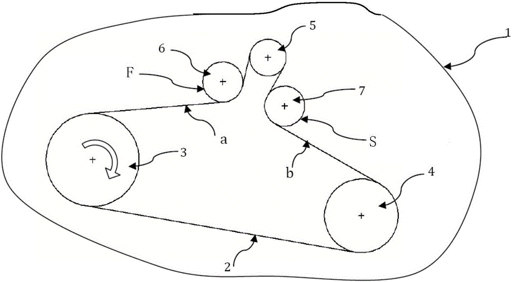
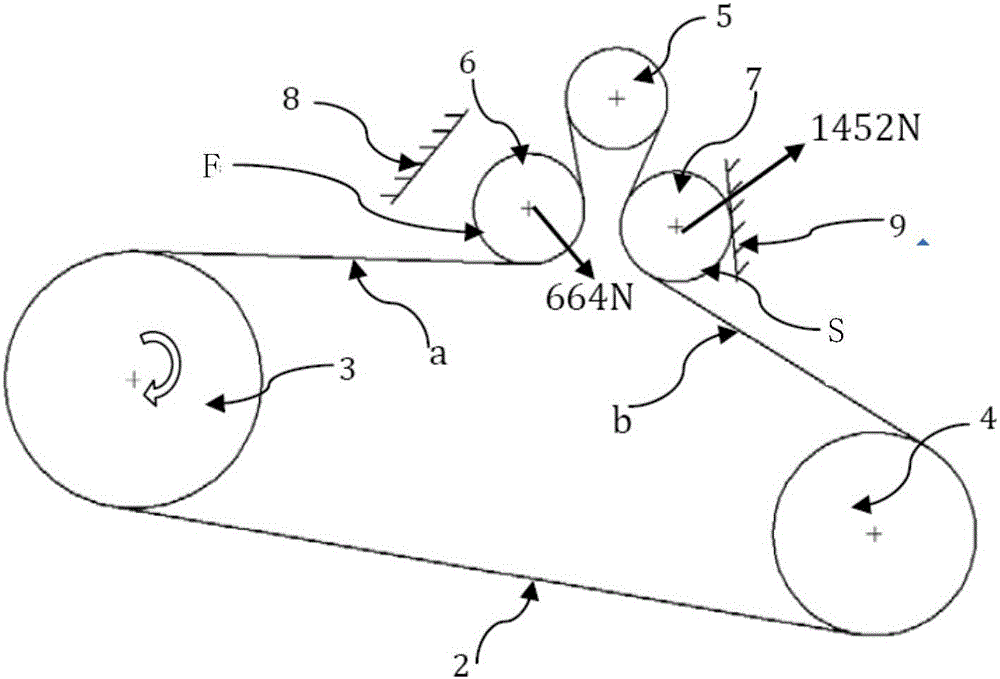
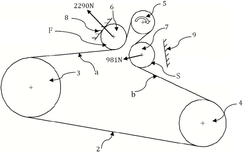
[0100] Figure 9 Another specific form of the invention is shown. The first tensioner 232 and the second tensioner 242 (in Figure 1-3 described as the first and second tensioners) are placed in positions that optimize the geometry of the wheel train. The two stop devices 82 and 92 are arranged according to an example of the invention. The position of the stop device on the tensioner is arranged differently according to the needs.

Embodiment 4

[0102] Figure 10 Another specific form of the invention is shown. Belt 2 is a synchronous conveyor belt (or timing belt), and the pulley can be a grooved pulley or a flat pulley. Also, in this case, the two stops will limit the movement of the tensioner. This solution can be used when the power / torque of the starter motor / generator is particularly large (close to or greater than 20KW). At the same time, the kinetic energy of the starter motor is not limited to start the engine, and the starter motor can also be used to drive the car for a certain kilometer number (micro-hybrid vehicle function).

[0103] It is necessary to mention an important situation concerning the transmission of the two tensioners that occurs on both sides of the generator: they separate the motion of the crankshaft and the generator. In fact, when the crankshaft decelerates, the moment of inertia of the generator tends to maintain the original speed and tension the band a ( figure 2 ) forces the fi...


PUM


Abstract

The invention relates to a conveying belt driving system mounted on an internal combustion engine which is provided with a reversible generator or a starting motor/generator, in particular to belt tensioning equipment of a hybrid electric vehicle. The belt tensioning equipment of the hybrid electric vehicle comprises a supporting disc, a first tensioning machine and a second tensioning machine, wherein the supporting disc is mounted at the front end of the starting motor/generator; the first tensioning machine and the second tensioning machine are mounted on the supporting disc; the two tensioning machines are similar in structure and each comprises a tensioning machine belt wheel and a tensioning arm; each tensioning machine belt wheel is mounted at one end of each tensioning arm; a pivot is arranged at the other end of each tensioning arm; each tensioning arm rotates around each pivot; each pivot is articulated with a shell; each shell and each tensioning machine belt wheel are positioned at the same side surface of each tensioning arm; a stopping device is arranged on each shell; each tensioning arm is provided with a check block matched with each stopping device.

Description

technical field [0001] The invention relates to a transmission belt driving system installed on an internal combustion engine with a reversible generator or a starter motor / generator, in particular to a belt tensioning device for a hybrid electric vehicle. Background technique [0002] In the patent DE19926615A1 (published on December 14, 2000), a tensioning device for traction is described, which contains two tensioning pulleys, wherein the swing axis of the tensioning arm of the two tensioning pulleys is connected to the drive pulley The drive shaft coincides. The tensioner consists of a flanged housing that supports the drive pulley bearing shaft. The disadvantages of this arrangement incorporating a drive shaft are twofold, the bearing shaft of the drive pulley must be supported by the flanged housing, and the design requires a significant increase in overall axial length. [0003] In the patent US7530911B2 (published on May 1, 2009), a tensioning device containing two...

Claims


Application Information

Patent Timeline
Patent Type & Authority Applications(China)
IPC IPC(8): F16H7/12
CPCF16H7/1281F16H2007/081F16H2007/0874F16H2007/0893F16H2007/0897
Inventor 蒋春雷马工王军成杨军歧陈讲虎
Owner NINGBO FENGMAO FAR EAST RUBBER
Why Eureka
Try Eureka