
Temperature detection device and method of power device as well as power device

A technology of a temperature detection device and a power device, which is applied in the detection field, can solve the problems of slow response, high cost, and low temperature detection accuracy, and achieves the effect of reducing the cost of use and accurate measurement

Inactive Publication Date: 2016-08-17
GREE ELECTRIC APPLIANCES INC
View PDF7 Cites 5 Cited by
  • Summary
  • Abstract
  • Description
  • Claims
  • Application Information

AI Technical Summary

Problems solved by technology

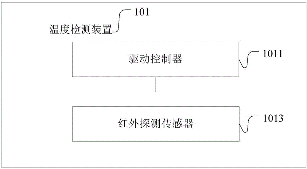
[0005] The main purpose of the present invention is to overcome the defects of the above-mentioned prior art, and propose a temperature detection device, method and power device of a power device to solve the problem of low accuracy, high cost and slow response in the temperature detection of power devices in the prior art. The problem

Method used


Image

  • Temperature detection device and method of power device as well as power device
  • Temperature detection device and method of power device as well as power device
  • Temperature detection device and method of power device as well as power device

Examples


Embodiment approach

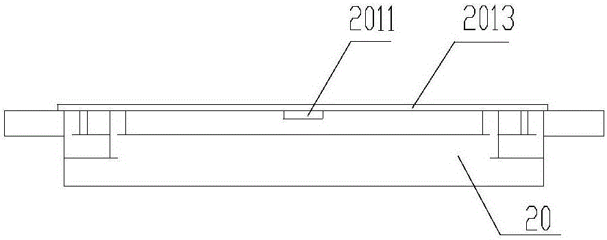
[0033] A specific embodiment of the present invention combines various aspects of other specific embodiments of the present invention. Such as image 3 shown.

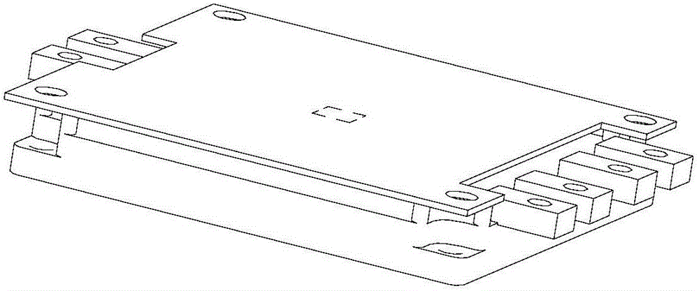
[0034] The front of the power device 20 is provided with a controller 2011 and an infrared detection sensor 2013 .

[0035] In this embodiment, the infrared detection sensor 2013 is arranged in the middle of the drive controller, and is controlled by the drive control circuit to collect the internal temperature of the power device 101 . The infrared detection sensor 2013 can accurately obtain the temperature of objects in the detection area, such as problems inside the power device, or the junction temperature of the power device.

[0036] Figure 4 It is a schematic diagram of the sensing area of ​​an infrared detection sensor according to an embodiment of the present invention. In order to improve detection accuracy and expand the sensing area of ​​the sensor, optionally, the infrared detection sensor may include...


PUM


Abstract

The invention provides a temperature detection device and method of a power device as well as the power device. The device comprises a drive controller and an infrared detection sensor, wherein the drive controller is mounted on the front side of the power device, and the infrared detection sensor is arranged in the drive controller, is controlled by a drive control circuit and acquires the internal temperature of the power device. With the adoption of the scheme, the internal temperature of the power device can be measured quickly and accurately, and the use cost of the power device can be reduced.

Description

technical field [0001] The invention relates to the detection field, in particular to a temperature detection device and method of a power device and the power device. Background technique [0002] Power devices, such as IGBT (Insulated Gate Bipolar Transistor), MOSFET (Metal Oxygen Semiconductor Field Effect Transistor), etc., have the characteristics of high voltage, high current, high frequency, and small on-resistance, and are widely used in inverter inverters. in the changing circuit. However, due to the poor overcurrent resistance and overvoltage resistance of power devices such as IGBTs, they will be damaged in case of an accident. For this reason, power devices such as IGBTs must be protected. Generally, the protection circuit design of power devices such as IGBTs is carried out from the three aspects of overcurrent, overvoltage and overheating. [0003] In the prior art, the temperature detection of power devices such as IGBT generally adopts the following method...

Claims


Application Information

Patent Timeline
Patent Type & Authority Applications(China)
IPC IPC(8): G01J5/00
CPCG01J5/00
Inventor 袁金荣蒋世用刘克勤张雪芬尤英帅
Owner GREE ELECTRIC APPLIANCES INC
Learn More