System and method for fast measuring explosive velocity during deep hole blasting on site

A technology of deep hole blasting and detonation velocity, which is applied in the direction of measuring the time required to move a certain distance, measuring device, fuel test, etc., and can solve problems such as extinguishment and detonation velocity drop

Active Publication Date: 2016-08-17
HONGDA MINING IND
View PDF7 Cites 13 Cited by
  • Summary
  • Abstract
  • Description
  • Claims
  • Application Information

AI Technical Summary

Problems solved by technology

If the density of explosives continues to increase, the detonation velocity will decrease. When the detonation velocity drops to

Method used


Image

  • System and method for fast measuring explosive velocity during deep hole blasting on site
  • System and method for fast measuring explosive velocity during deep hole blasting on site

Examples


Embodiment 1

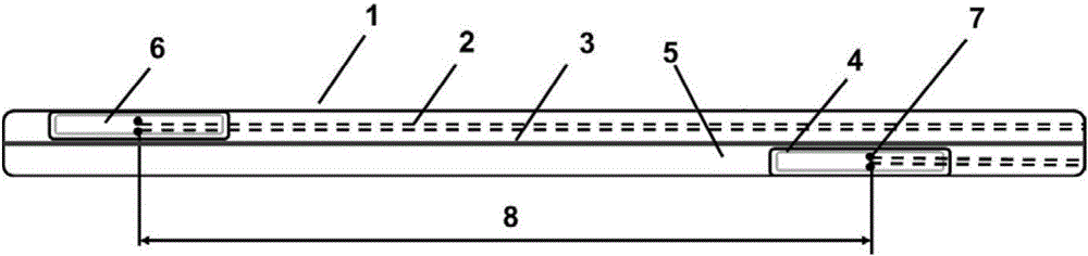
[0037] To quickly measure the detonation velocity of explosives in deep hole blasting on site, it is first necessary to make figure 1 The detonation velocity detection device shown is processed by a network cable 1. The network cable 1 includes four sets of twisted thin wires 2, a cross 3, a shielding layer 4 and a sheath 5. The cross 3 is arranged on In the center of the network cable 1, the four groups of thin wires 2 twisted into a twisted shape are evenly distributed on the cross 3, and the shielding layer 4 wraps the cross 3 and the four groups of thin wires 2 twisted into a twisted shape. The sheath 5 is wrapped on the outside of the shielding layer 4; wherein, each set of twisted thin wires 2 has two, the shielding layer 4 is an aluminum foil shielding layer, and the sheath 5 is a polyvinyl chloride sheath.

[0038]When the detonation speed detection device is being processed, first cut a gap 6 in the sheath 5 of the network cable 1 with a utility knife at a distance of...

Embodiment 2

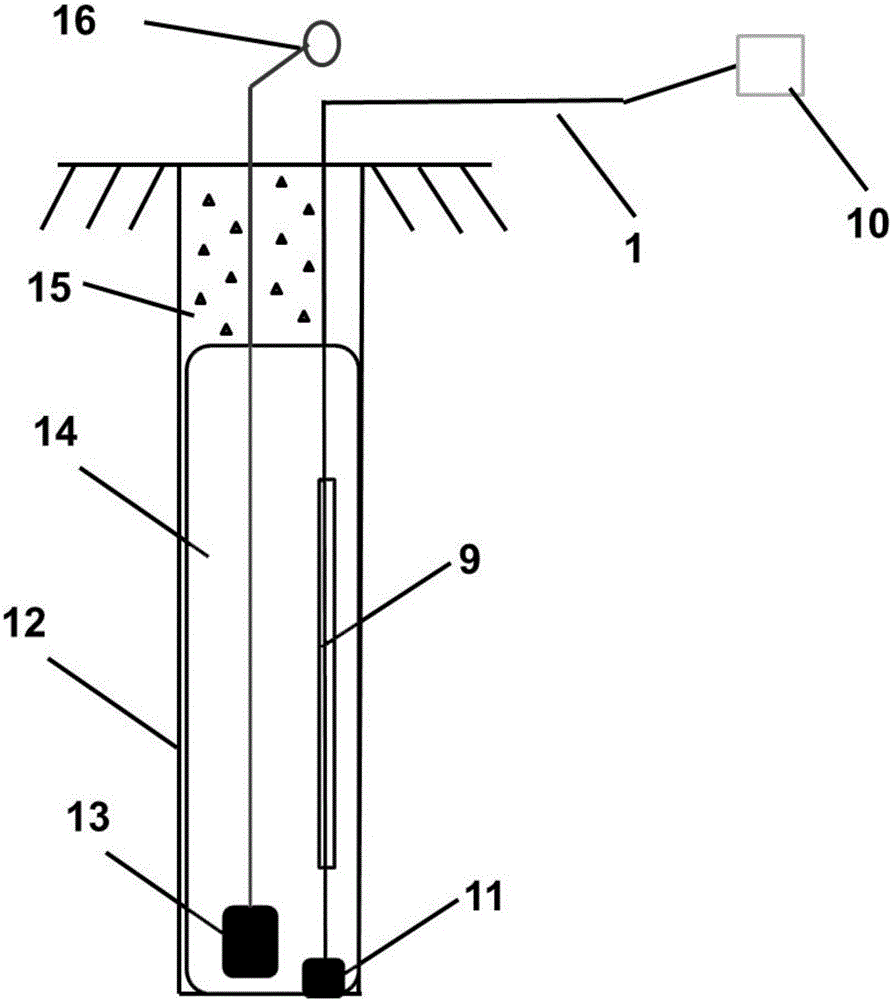
[0042] The system for quickly measuring the detonation velocity of explosives during deep hole blasting in this embodiment uses four sets of twisted thin wires in the network cable to quickly and conveniently process the detonation velocity test probe in the hole, that is, each group of thin wires is cut in the middle to form The detonation velocity test probe in the disconnected state can process four sets of detonation velocity test probes in total. The ionosphere generated during the explosion reaction of the explosive conducts the detonation velocity test probe embedded in the explosive, and changes from the disconnected state to the conductive state. , so as to send a trigger electrical signal; at the same time, use the thin wire group itself as the transmission branch line in the hole of the test signal, use the network cable itself to transmit the main line of the signal outside the hole of the test signal, use the shielding layer to shield the field stray signal, and use...


PUM


Abstract

The invention discloses a system and method for fast measuring explosive velocity during deep hole blasting on site. The system comprises an explosive velocity detecting device, a priming device, explosive and stemming which are placed in a blast hole, one end of the explosive velocity detecting device is connected with a multi-section explosive velocity instrument, the other end of the explosive velocity detecting device is connected with a balance weight, the multi-section explosive velocity instrument is placed in a safe region outside the blast hole, and the balance weight is placed at the bottom of the blast hole and pulled straightly; the distance between the priming device and the bottom of the blast hole is smaller than that between the explosive velocity detecting device and the bottom of the blast hole, the explosive velocity detecting device, the balance weight and the priming device are embedded in the explosive, and the stemming is located on the explosive. The phenomenon that an ionized layer is generated in the explosion reaction process of the explosive, explosive velocity detecting probes embedded in the explosive are connected and changed into the connected state from the disconnected state, a triggering electric signal is emitted out, and the distance between the two adjacent explosive velocity detecting probes is divided by time difference of the corresponding triggering signal to obtain explosive velocity of the explosive in the blast hole.

Description

technical field [0001] The invention relates to a system and method for measuring the detonation velocity of explosives, in particular to a system and method for quickly measuring the detonation velocity of explosives in deep hole blasting on site, belonging to the technical field of engineering blasting. Background technique [0002] It is generally believed that when the wave impedance of the explosive matches that of the rock, the energy transmitted by the explosive to the rock is the most, and the strain value induced in the rock is the largest, and a better blasting effect can be obtained. In order to obtain the matching relationship between explosive and rock wave impedance, four physical quantities, namely explosive density, explosive detonation velocity, rock density and rock sound velocity, need to be measured respectively. In general, explosive density and rock density can be obtained by weighing and volume measurement, rock sound velocity can be obtained by sound ...

Claims


Application Information

Patent Timeline
IPC IPC(8): G01P3/66G01N33/22
CPCG01N33/227G01P3/66
Inventor 崔晓荣林谋金开俊俊汪旭光李战军宋锦泉
Owner HONGDA MINING IND
Why Eureka
Try Eureka