Flexible hinge beam fiber Bragg grating two-dimensional acceleration sensor

An acceleration sensor, fiber Bragg technology, applied in multi-dimensional acceleration measurement, acceleration measurement using inertial force, etc., to achieve the effect of convenient downhole, large dynamic range and small volume

Inactive Publication Date: 2016-08-17
XI'AN PETROLEUM UNIVERSITY
View PDF9 Cites 12 Cited by
  • Summary
  • Abstract
  • Description
  • Claims
  • Application Information

AI Technical Summary

Problems solved by technology

[0005] The technical problem to be solved by the present invention is to overcome the shortcomings of existing fiber Bragg grating acceleration sensors and provide a flexible hinged beam fiber optic Bragg grating two-dimensional acceleration sensor with simple structure, small volume, high temperature resistance and large measurement frequency range

Method used


Image

  • Flexible hinge beam fiber Bragg grating two-dimensional acceleration sensor
  • Flexible hinge beam fiber Bragg grating two-dimensional acceleration sensor
  • Flexible hinge beam fiber Bragg grating two-dimensional acceleration sensor

Examples


Embodiment 1

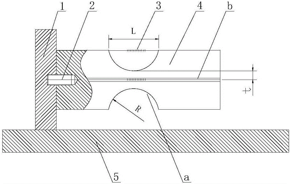
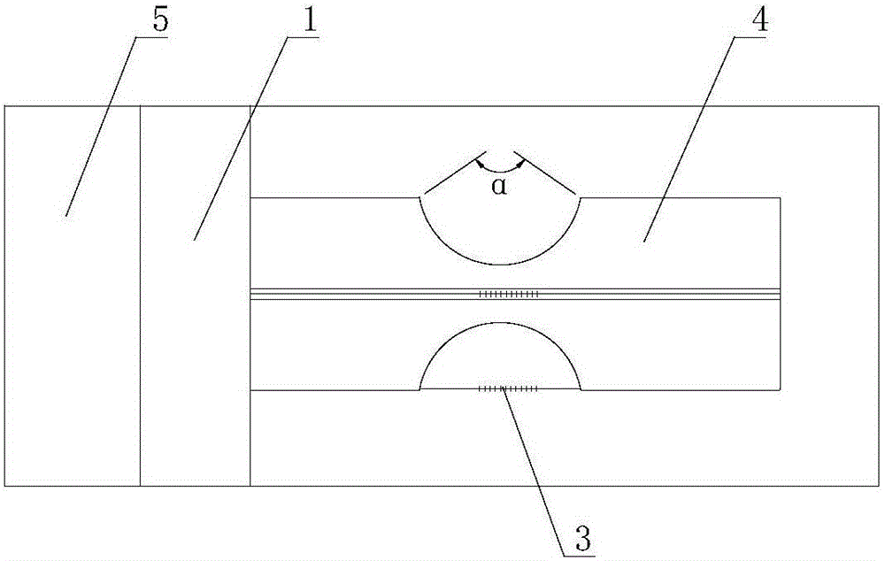
[0019] exist figure 1 , 2 , 3, the flexible hinge beam fiber Bragg grating two-dimensional acceleration sensor of this embodiment is composed of a support 1 , a screw 2 , a fiber Bragg grating 3 , a flexible hinge beam 4 , and a base 5 . One side of the base 5 is fixedly connected with a support 1 with a threaded fastening connector, and a cylindrical flexible hinge beam 4 is connected with a screw 2 on the support 1. The material of the flexible hinge beam 4 is 304 stainless steel, and the circumference of the flexible hinge beam 4 is The cross-sectional geometric shape of the measuring groove a in the direction is an arc, the central angle α opposite the arc is 90°, and the radius of the arc is:

[0020] R = L 2 s i n α 2

[0021] In the formula, L is the length of the grid area of ​​the fiber Brag...

Embodiment 2

[0030] In this embodiment, the cross-sectional geometric shape of the measuring groove a in the circumferential direction of the flexible hinge beam 4 is an arc, the central angle α to which the arc is opposite is 30°, and the radius of the arc is:

[0031] R = L 2 s i n α 2

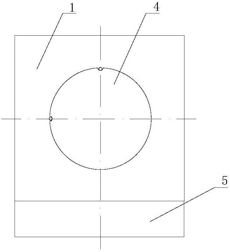
[0032] In the formula, L is the length of the grid area of ​​the fiber Bragg grating 3, and α is the central angle of the arc. The difference t between the radius of the flexible hinged beam 4 and the depth of the measuring groove a is 0.25mm. Two optical fiber installation grooves b are processed axially on the outer surface of the flexible hinged beam 4. The angle between them is 90°. Fiber Bragg grating 3 is encapsulated with 502 glue or epoxy resin glue in fiber installation groove b. The grating part of fiber Bragg grating 3...

Embodiment 3

[0034] In this embodiment, the circumferential direction of the flexible hinge beam 4 is processed with a measuring groove a, the cross-sectional geometric shape of the measuring groove a is a circular arc, the central angle α of the circular arc is 180°, and the radius of the circular arc is:

[0035] R = L 2 s i n α 2

[0036] In the formula, L is the length of the grid region of the fiber Bragg grating 3, and α is the central angle of the arc. The difference t between the radius of the flexible hinged beam 4 and the depth of the measuring groove a is 1.5mm. Two optical fiber installation grooves b are machined on the outer surface of the flexible hinged beam 4 along the axial direction. The angle between them is 90°. Fiber Bragg grating 3 is encapsulated with 502 glue or epoxy resin glue in fiber in...


PUM


Abstract

The invention provides a flexible hinge beam fiber Bragg grating two-dimensional acceleration sensor. One side of the base is provided with a support base which is connected to a cylindrical flexible hinge beam by using a screw. A measurement groove is processed in the circumferential direction of the flexible hinge beam, and the depth of the measurement groove is smaller than the radius of the flexible hinge beam. Two fiber mounting grooves are processed along the axial direction at the outer surface of the flexible hinge beam. The angle between the sections where two fiber mounting groove center lines are located is 90 degrees. Fiber Bragg gratings are bonded in the fiber mounting grooves by using glue, and the grating parts of the fiber Bragg gratings are above the measurement groove. The flexible hinge beam fiber Bragg grating two-dimensional acceleration sensor of the invention has the advantages of high temperature resistance, a simple structure, easy manufacture, a small size and easy going down and can be used in the fields of downhole seismic wave exploration and micro-seismic monitoring technology.

Description

technical field [0001] The invention belongs to the technical field of measuring acceleration, and in particular relates to a device for measuring acceleration in two-dimensional space. Background technique [0002] The basic principle of the fiber Bragg grating acceleration sensor is to use the external vibration signal acting on the sensor structure to couple to the fiber Bragg grating, causing the change of the fiber Bragg grating period and effective refractive index, and the drift of the center wavelength of the fiber Bragg grating through demodulation The frequency and amplitude of the external signal can be detected indirectly. In recent years, the measurement of vibration signals by fiber optic sensors has attracted widespread attention at home and abroad, especially in the application fields of large-scale civil engineering structure health monitoring, oil and gas field exploration, interwell seismic wave exploration and microseismic fracture monitoring technology. ...

Claims


Application Information

Patent Timeline
Patent Type & Authority Applications(China)
IPC IPC(8): G01P15/18
CPCG01P15/18
Inventor 乔学光张芸山高宏刘钦朋禹大宽邵敏王向宇李辉栋
Owner XI'AN PETROLEUM UNIVERSITY
Why Eureka
Try Eureka