Ultrasonic emission channel time-delay control module

A delay control and ultrasonic transmission technology, applied in the field of ultrasonic phased array, can solve the problems of occupying FPGA internal resources, increasing system cost, occupying a large buffer space, etc., to achieve the effect of reducing FPGA resources and improving system cost performance

Inactive Publication Date: 2016-08-17
WUXI HAIYING ELECTRONICS MEDICAL SYST
View PDF11 Cites 1 Cited by
  • Summary
  • Abstract
  • Description
  • Claims
  • Application Information

AI Technical Summary

Problems solved by technology

[0006] The traditional transmission module uses a delay counter for each transmission channel. The delay control module controls the delay counter to count according to the main clock. When the count value reaches the specified delay parameter, the trigger channel is enabled for transmission, and the 32 channels are 32 delay counters are required, occupying a large amount of buffer space, occupying a large amount of internal resources of the FPGA, increasing the system cost, and greatly reducing the cost performance of the system. In the high-precision delay module, the buffer space occupied by 32 counters is more Big

Method used


Image

  • Ultrasonic emission channel time-delay control module
  • Ultrasonic emission channel time-delay control module
  • Ultrasonic emission channel time-delay control module

Examples


Embodiment Construction

[0018] The embodiments listed in the present invention are only used to help understand the present invention, and should not be interpreted as limiting the protection scope of the present invention. For those of ordinary skill in the art, they can also Improvements and modifications are made to the present invention, and these improvements and modifications also fall within the protection scope of the claims of the present invention.

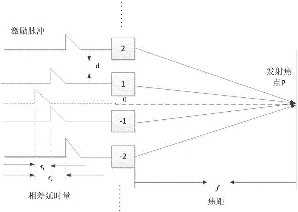
[0019] Assuming there is a 128-element, 32-channel system, the focus of its emission focus can be achieved by setting different delays for each channel, such as image 3 Schematic diagram of linear array time-lapse focusing. In order to achieve focusing, the array element farthest from the center of the array element is first excited to generate ultrasonic emission, and then the ultrasonic emission is delayed in the order of approaching the center of the array element. For the sake of simplicity, only 4 array elements are drawn in the figure, ...


PUM


Abstract

The invention relates to an ultrasonic emission channel time-delay control module. The ultrasonic emission channel time-delay control module comprises an external controller PC, a time-delay parameter reading-writing bus, an FPGA chip internal block RAM, a plurality of channels, a high-voltage pulse forming module and a probe, and further comprises a counter and a plurality of comparers corresponding to the channels, wherein the FPGA chip internal block RAM loads a time-delay parameter ti to one input end of the comparers corresponding to the channels, and simultaneously loads a maximum value and a minimum value of the time-delay parameter ti to the counter to form a counting range of the counter; a real-time counting value of the counter is loaded to the other input end of the comparers; the comparers compare the real-time counting value of the counter with a time-delay parameter value, and if the real-time counting value of the counter is equal to the time-delay parameter value, the time-delay time of each channel is up, and the comparers output enabling levels to trigger the corresponding channels. According to the ultrasonic emission channel time-delay control module, occupied FPGA resources are reduced, and the cost performance of a system is improved.

Description

technical field [0001] The invention relates to the technical field of ultrasonic phased arrays, in particular to an ultrasonic transmission channel delay control module. Background technique [0002] The ultrasound system includes ultrasound probe 1, T / R switch 2, ultrasound reception 3, reception beamforming 4, signal processing and image display 5, transmission drive 6, transmission waveform generation 7, transmission delay control 8, and scanning control 9. like figure 1 Block diagram of the ultrasound system. The transmission delay control 8 controls the generation of the transmission waveform 7, and forms a high-voltage pulse through level conversion, which excites the probe 1, and the probe 1 converts electric energy into sound energy and transmits it. The probe 1 converts the received echo pulses into electrical energy, undergoes ultrasonic reception 3 , receives beam synthesis 4 , and then performs signal processing and image display. [0003] Converging and conv...

Claims


Application Information

Patent Timeline
Patent Type & Authority Applications(China)
IPC IPC(8): G01S7/52
CPCG01S7/52
Inventor 朱振超
Owner WUXI HAIYING ELECTRONICS MEDICAL SYST
Why Eureka
Try Eureka