Side-slot-reinforced leading-in optical cable and production process

A fiber optic cable introduction and enhanced technology, which is applied in the field of side groove reinforced fiber optic cable introduction and production technology, can solve the problems of weak protection at the optical fiber, hydrogen loss of the optical fiber, and damage to the optical cable, and achieve overall strength enhancement, wall thickness increase, and wall thickness. Increased effect

Inactive Publication Date: 2016-08-17
SHENYANG HENGTONG OPTICAL COMM CO LTD
View PDF13 Cites 3 Cited by
  • Summary
  • Abstract
  • Description
  • Claims
  • Application Information

AI Technical Summary

Problems solved by technology

The traditional butterfly-shaped lead-in cable is unavoidably curled, twisted or stressed unevenly during construction in urban areas, suburbs and villages with dense trees. The connection point corresponding to the side slot, and the connection point is facing the optical fiber, and the measures to protect the optical fiber are quite weak. There is no other material except a thin layer of sheath, and the protection of the optical fiber is extremely poor.
The slotting was originally designed to facilitate the stripping of the optical cable and take out the optical fiber, but it is easy to be torn apart due to force during the construction process, which is prone to water seepage, causing hydrogen damage to the optical fiber, increasing the attenuation coefficient of the optical fiber, and reducing the service life of the optical fiber.
At the same time, in some areas where there are many insects, because the protection of the optical fiber in the optical cable is weak, the optical cable will be damaged by insects after construction.
Because the slots are convenient for insects to stay and hide, insects especially like to lay eggs in the slots of the optical cable. The insects use the butterfly-shaped black outer sheath of the optical cable as a withered tree trunk. The thorn in the middle of the oviduct rubs repeatedly on the surface of the rough optical cable, and under the action of friction, the surface of the optical cable is worn to form a certain small hole, and then starts 180° reciprocating rotating friction, and the hole is worn and enlarged through the serrated oviposition tube until the hole The size and depth are suitable for laying eggs. Because the optical fiber protection at the slot of the traditional butterfly optical cable is weak, it is easy to pierce the outer sheath of the optical cable, damage the optical fiber, and affect normal information communication.
After long-term production and practice, the traditional butterfly drop cable is no longer suitable for popularization and use in many practical applications. It is necessary to develop a drop cable that meets more structural requirements and performance requirements to improve the reliability and reliability of the user drop cable. applicability

Method used


Image

  • Side-slot-reinforced leading-in optical cable and production process
  • Side-slot-reinforced leading-in optical cable and production process

Examples


example 1

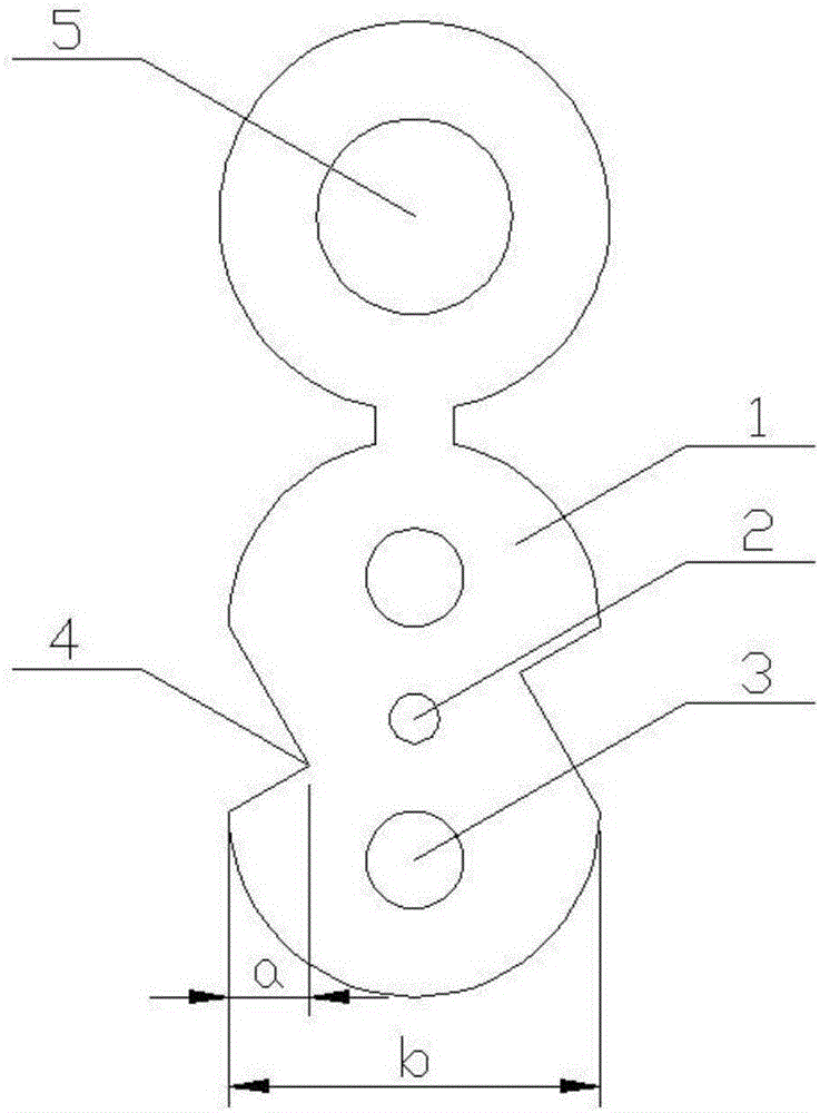
[0027] This implementation is a self-supporting side slot reinforced lead-in cable, including optical fiber 2, playground-type sheath 1, reinforcement 3 and suspension wire 5, the outer side of the optical fiber 2 is wrapped with playground-type sheath 1, and the playground-type sheath 1. A diagonal side groove 4 is arranged on the straight side. The diagonal side groove 4 is a triangular groove. An optical fiber 2 is arranged at the center of the playground-type sheath 1, and symmetrically arranged on both sides of the optical fiber 2. Reinforcement 3 at the round end of the playground sheath 1 . The depth of the oblique side groove 4 is smaller than the thickness between the bottom of the groove and the optical fiber. The depth a of the oblique side groove accounts for 20%-30% of the width b of the playground sheath. The upper end of one side of the circular end of the playground-shaped sheath 1 is provided with a suspension wire 5 , and the outer side of the suspension wir...

example 2

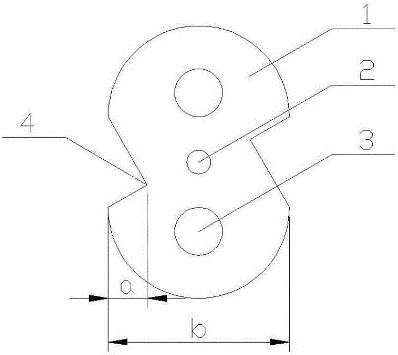
[0035] This implementation is a kind of side groove reinforced lead-in optical cable, including optical fiber 2 and strength member 3, the outer side of the optical fiber 2 is wrapped with a playground-type sheath 1, and a diagonal side groove is arranged on the straight side of the playground-type sheath 1 4. The obliquely opposite side groove 4 is a triangular groove, an optical fiber 2 is arranged at the center of the playground-type sheath 1, and reinforcing members 3 placed at the round ends of the playground-type sheath are symmetrically arranged on both sides of the optical fiber 2 . The depth of the oblique side groove 4 is smaller than the thickness between the bottom of the groove and the optical fiber 2 . The depth a of the oblique side groove accounts for 20%-30% of the width b of the playground sheath.

[0036] A production process for a side slot reinforced drop-in optical cable, which includes the following process steps: Step 1 removes the suspension wire 5 on ...


PUM


Abstract

The invention provides a side-slot-reinforced leading-in optical cable and a production process. The side-slot-reinforced leading-in optical cable comprises an optical fiber, a sheath and reinforcement pieces and is characterized in that the playground type sheath covers the outer side of the optical fiber; diagonal side slots are formed in straight side surfaces of the playground type sheath and are triangular slots; the optical fiber is arranged at the center of the playground type sheath; the reinforcement pieces are placed on the circular ends of the playground type sheath and are symmetrically arranged on the two sides of the optical fiber. According to the side-slot-reinforced leading-in optical cable and the production process, the utilized side slots are diagonally staggered, and a stress centralizing point avoids the optical fiber, so that walls on the two sides of the optical fiber are thickened; the optical fiber is protected, the integral wall thickness of the optical cable is increased, and the improvement on the integral strength of the optical cable is ensured; by means of the designed staggered side slots, tearing of slotted parts due to the weight outdoors for a long term can be avoided; according to application environments, the tearing force of the optical cable can be freely controlled; the effective section area is further shortened, and the utilization rate of materials is further increased; a prefabricated end forming process and the traditional butterfly-shape leading-in optical cable are not different and can match with the existing devices.

Description

technical field [0001] The invention relates to the technical field of optical cable covering, in particular to a side groove reinforced drop optical cable and a production process. Background technique [0002] With the vigorous development of FTTH, the broadband China strategy is in full swing. Butterfly lead-in optical cables are widely used in cities and villages in my country. The traditional butterfly-shaped lead-in cable is unavoidably curled, twisted or stressed unevenly during construction in urban areas, suburbs and villages with dense trees. The connection point corresponding to the side slot, and the connection point is facing the optical fiber, and the measures to protect the optical fiber are quite weak, except for a very thin sheath, there is no other material, and the protection for the optical fiber is extremely poor. The slotting was originally designed to facilitate the stripping of the optical cable and take out the optical fiber, but it is easy to be t...

Claims


Application Information

Patent Timeline
Patent Type & Authority Applications(China)
IPC IPC(8): G02B6/44
CPCG02B6/443G02B6/4433G02B6/4479G02B6/4486
Inventor 谢松年薛梦驰施李萍张少田王志山李越辛文惠张宪恒闫旭光来庆阳
Owner SHENYANG HENGTONG OPTICAL COMM CO LTD
Why Eureka
Try Eureka