Thermal loading device and thermal loading method for variable acceleration environmental test

An environmental test, variable acceleration technology, applied in the direction of temperature control, non-electric variable control, instruments, etc., can solve the problems of maximum temperature, temperature rise rate limit, poor anti-oxidation performance, short circuit of heating wire, etc., to achieve uniform temperature control The effect of good performance, good insulation and high heating index

Active Publication Date: 2017-09-15
GENERAL ENG RES INST CHINA ACAD OF ENG PHYSICS
View PDF4 Cites 0 Cited by
  • Summary
  • Abstract
  • Description
  • Claims
  • Application Information

AI Technical Summary

Problems solved by technology

This device can complete the steady-state acceleration-temperature composite environmental test assessment, but it is not suitable for temperature-acceleration environmental tests in variable acceleration environments in terms of temperature rise range, temperature and acceleration change rate, and safety. The temperature resistance of the tetrafluoroethylene heating film does not exceed 100 degrees. Therefore, the maximum temperature and the rate of temperature rise must be limited; the heating film is attached to the inner wall of the container with high-temperature glue. If you want to replace the heating film in this installation method, it is very difficult. Difficult; PTFE is a kind of plastic, which is easily deformed or even melted by mechanical force and thermal stress under variable acceleration and high temperature environment. The inside of the heating film may also be degummed due to high temperature, causing short circuit of the heating wire contained inside. , a safety accident occurred
In addition, the anti-wear performance, durable applicability and oxidation resistance of plastics are poor, which is likely to cause safety hazards

Method used


Image

  • Thermal loading device and thermal loading method for variable acceleration environmental test
  • Thermal loading device and thermal loading method for variable acceleration environmental test

Examples


Embodiment Construction

[0018] The present invention will be further explained below in conjunction with the drawings:

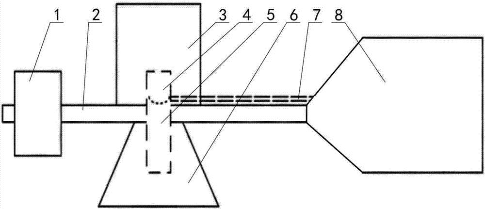
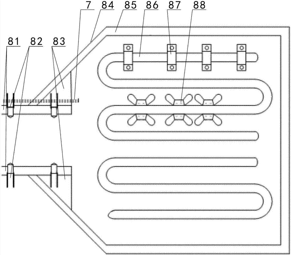
[0019] Such as figure 2 As shown, the thermal loading device for variable acceleration environmental test of the present invention includes a temperature control box (not shown in the figure), a temperature sensor 7, a thermal loading box 84, a heating tube 86, a rotating arm connecting support plate 81, and a corundum heat insulation card Hoop 87 and petal-shaped radiating fin 88, the wall of the heat loading box 84 is a sandwich stainless steel plate, the sandwich of the sandwich stainless steel plate is filled with insulation wool 85, the heating tube 86 is two independent sections, each section of heating tube 86 is horizontally installed in the heat loading box 84, the sensing end of the temperature sensor 7 is placed in the heat loading box 84, the signal output end of the temperature sensor 7 and the input ends of the two sections of heating pipe 86 are respectively connected ...


PUM


Abstract

The invention discloses a thermal loading device for a variable-accelerated-speed environment test. A heating tube is arranged in a thermal loading box, the induction end of a temperature sensor is arranged in the thermal loading box, the signal output end of the temperature sensor and the input end of the heating tube are correspondingly connected with a temperature control box, the heating tube is filled with magnesium oxide, the two ends of the heating tube are sealed with ceramics, the heating tube is mounted to the inner wall of the thermal loading box through multiple thermal-insulation clamps, multiple cooling fins are mounted on the heating tube, and tumbler connecting and supporting plates are mounted on a box opening of the thermal loading box and used for being connected with a tumbler of a centrifugal machine in a seamless mode. The invention further discloses a thermal loading method adopted by the thermal loading device for the variable-accelerated-speed environment test, and a double-temperature-zone thermal loading method or a response temperature method is adopted. According to the thermal loading device and method for the variable-accelerated-speed environment test, the heating tube is filled with magnesium oxide, and the cooling fins are mounted, so that the device has better heat dissipation performance; through the temperature control box, the temperature sensor and the heating tube, precision control over the temperature inside the thermal loading box is achieved.

Description

Technical field [0001] The invention relates to a device for a variable acceleration environment test, in particular to a thermal loading device and a thermal loading method for a variable acceleration environment test. Background technique [0002] During the flight process, the aircraft needs to accelerate, decelerate and maneuver. It is subject to variable accelerations from various directions and different magnitudes. At the same time, the temperature load experienced during the variable acceleration flight also changes greatly. For example, the temperature changes caused by different atmospheric environments constitute the aircraft during flight. The variable acceleration-temperature compound environment to be experienced. When the flying speed of the aircraft reaches or exceeds 5 times the sound travel (such as supersonic aircraft), the variable acceleration generated by the aircraft maneuver is more obvious. At the same time, the kinetic energy of the fast flying air is c...

Claims


Application Information

Patent Timeline
Patent Type & Authority Patents(China)
IPC IPC(8): G05D23/20
CPCG05D23/20
Inventor 鲁亮胜来欧峰
Owner GENERAL ENG RES INST CHINA ACAD OF ENG PHYSICS
Why Eureka
Try Eureka