
Multi-target optimization design method for machine tool cross beam on basis of orthogonal test analysis

A multi-objective optimization and orthogonal test technology, which is applied in the multi-objective optimization design of machine tool beams based on orthogonal test analysis and the design of key structures of machine tools, can solve the problem of selecting the optimal parameter combination by the orthogonal test method. plan, and did not directly propose structural improvement measures for the weak link of the beam, so as to achieve the effect of reducing the maximum coupling deformation, reducing the number of tests, and simplifying the operation.

Active Publication Date: 2016-08-17
南京黄石机床制造有限公司
View PDF5 Cites 21 Cited by
  • Summary
  • Abstract
  • Description
  • Claims
  • Application Information

AI Technical Summary

Problems solved by technology

The optimization design of the beam in the above-mentioned patent mainly focuses on the structure and size of the rib plate of the beam, and does not directly propose structural improvement measures related to the weak link of the beam, nor does it see a plan to use the orthogonal test method to select the optimal parameter combination

Method used


Image

  • Multi-target optimization design method for machine tool cross beam on basis of orthogonal test analysis
  • Multi-target optimization design method for machine tool cross beam on basis of orthogonal test analysis
  • Multi-target optimization design method for machine tool cross beam on basis of orthogonal test analysis

Examples


Embodiment Construction

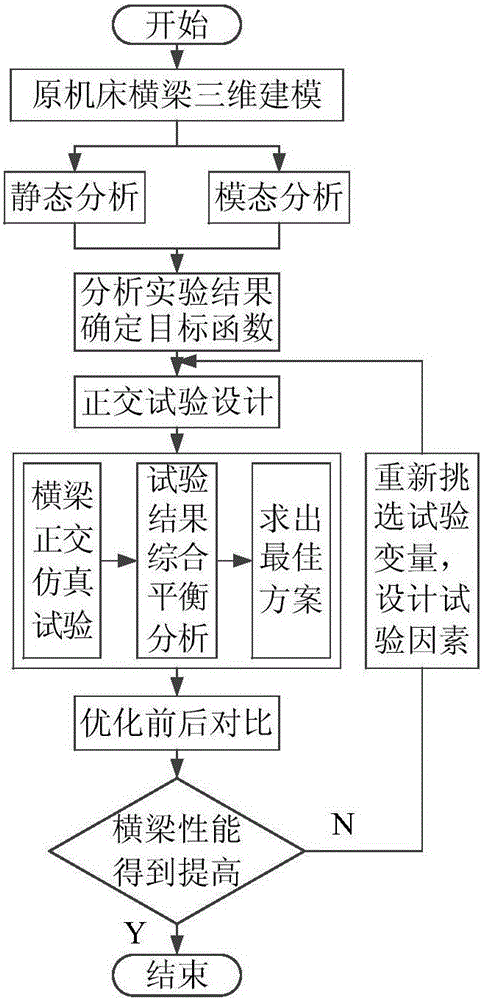
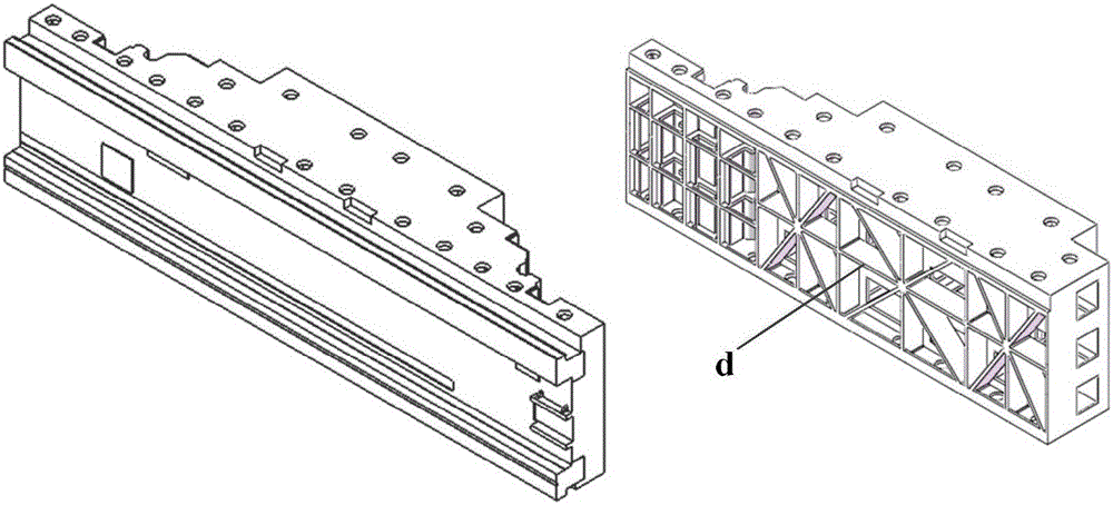
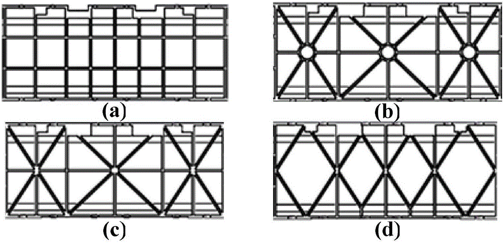
[0027] Such as figure 1 Shown is the flowchart of the method of the present invention. First, carry out three-dimensional modeling of the original moving beam, simulate the static and dynamic mechanical properties of the beam according to the actual working conditions, and analyze the simulation data to obtain the objective function of the optimal design of the beam, that is, to determine the factors that affect the performance of the beam: beam rib structure, rib Thickness, upper guide rail support rib structure, and determine the evaluation indicators for evaluating the performance of beams: beam quality, maximum coupling deformation, maximum coupling stress, and first-order natural frequency.

[0028] Orthogonal experimental design is then carried out: determine the experimental factors, and select the number of levels for each factor. In the present invention, the number of factors is 3, and the number of levels is 4, and an orthogonal test of three factors and four level...


PUM


Abstract

The invention discloses a multi-target optimization design method for a machine tool cross beam on the basis of orthogonal test analysis. According to the method, designing is conducted from the three aspects including the cross beam rib plate structure, the rib plate thickness and the inclined angle formed when a guide rail arranged on the cross beam supports a rib plate. The method comprises the following steps that three-dimensional modeling is conducted on an original cross beam, and the static and dynamic characteristics of the original cross beam are analyzed to determine cross beam optimization factors and evaluation indexes; the cross beam rib plate structure, the rib plate thickness and the inclined angle formed when the guide rail arranged on the cross beam supports the rib plate are selected as test factors, the levels of all the factors are determined, a simulation test is conducted on a combination of all the factors by selecting an orthogonal test table, and analytical processing is conducted on simulation data through a comprehensive balance analysis method to obtain an optimal parameter combination; the rationality of the optimization design parameter combination is determined by comparing all the properties of the cross beam before optimization with all the properties of the cross beam after optimization. According to the optimization design method, the optimization test parameter combination is obtained through small test time number, and the method is reasonable, feasible and easy to operate and has the typicality and symmetrical comparability.

Description

technical field [0001] The invention belongs to the field of mechanical design, and relates to a design method for a key structure of a machine tool, in particular to a multi-objective optimization design method for a machine tool beam based on orthogonal test analysis. Background technique [0002] As a machine for manufacturing machines, CNC machine tools are widely used in aerospace, ship machinery, large molds, automobile manufacturing and other industries. With the innovation of technology and the upgrading of products, the requirements for the machining accuracy of CNC machine tools are getting higher and higher. Among them, the beam of the machine tool is an important supporting part of the machine tool parts, and its performance directly affects the machining accuracy of the machine tool. [0003] Traditional beam design methods mostly use sensitivity analysis method and topology optimization method, and the targets of optimization design mainly focus on beam rib str...

Claims


Application Information

Patent Timeline
Patent Type & Authority Applications(China)
IPC IPC(8): G06F17/50
CPCG06F30/17G06F30/367
Inventor 邱自学鞠家全袁江周成一陆观邵建新
Owner 南京黄石机床制造有限公司
Learn More