
Locomotive speed sensor signal filtering device

A speed sensor and signal filtering technology, applied in signal transmission systems, instruments, etc., to achieve the effect of eliminating rising edge jitter and falling edge jitter

Active Publication Date: 2016-08-17
邳州市景鹏创业投资有限公司
View PDF5 Cites 0 Cited by
  • Summary
  • Abstract
  • Description
  • Claims
  • Application Information

AI Technical Summary

Problems solved by technology

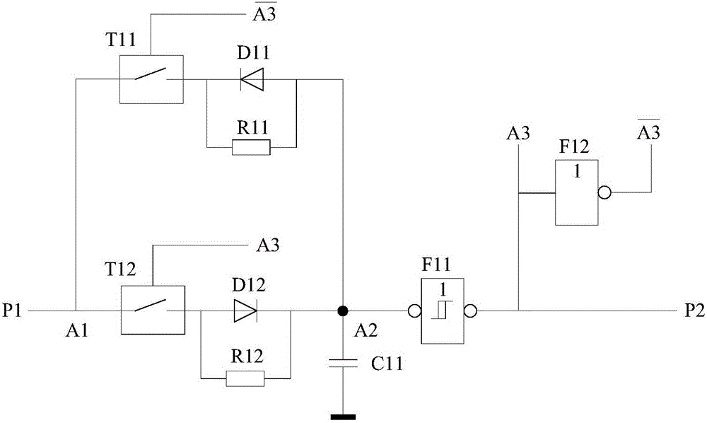
[0003] In order to solve the problems existing in the existing locomotive speed sensor signal, the present invention provides a locomotive speed sensor signal filtering device, including a fast discharge circuit, a fast charge circuit, a charge and discharge resistor, a capacitor, and a Schmidt circuit

Method used


Image

  • Locomotive speed sensor signal filtering device
  • Locomotive speed sensor signal filtering device
  • Locomotive speed sensor signal filtering device

Examples


Embodiment 5

[0047] In Embodiment 5, the charge resistor and discharge resistor connected in parallel with the fast discharge diode and the fast charge diode respectively are cancelled, and are replaced by the charge and discharge resistor R51 connected in parallel with the input pulse terminal E1 and the input terminal E2 of the Schmidt circuit. This circuit is a special case where the charging resistor and the discharging resistor are the same, which can simplify the circuit structure.

[0048] Figure 8 Shown is Embodiment 6 of the locomotive speed sensor signal filtering device. In Embodiment 6, the fast discharge diode is a diode D61, the fast charge diode is a diode D62, the fast discharge switch and the fast charge switch are digitally controlled multi-channel analog switches T61; the capacitor is a capacitor C61, and one end of the capacitor C61 is connected to a Schmitt circuit The input end of F61 is the input end F2 of F61, and the other end is connected to the common ground; t...

Embodiment 6

[0049] In Embodiment 6, the charging and discharging resistors connected in parallel with the fast-discharging diode and the fast-charging diode respectively are canceled and replaced by the charging and discharging resistor R61 connected in parallel with the input pulse terminal F4 and the Schmidt circuit input terminal F2. This circuit is also a special case where the charging resistor and the discharging resistor are the same, which can simplify the circuit structure.

[0050] The input signal of the Schmidt circuit is the voltage on the capacitor, therefore, the Schmidt circuit is required to have a high input impedance characteristic. Schmitt circuit can choose CMOS Schmitt inverter CD40106, 74HC14 with high input impedance characteristics, or choose CMOS Schmitt NAND gate CD4093, 74HC24 and other devices with high input impedance characteristics. The upper threshold voltage and lower threshold voltage of CMOS Schmitt inverter or CMOS Schmidt NAND gate are fixed values ​​...


PUM


Abstract

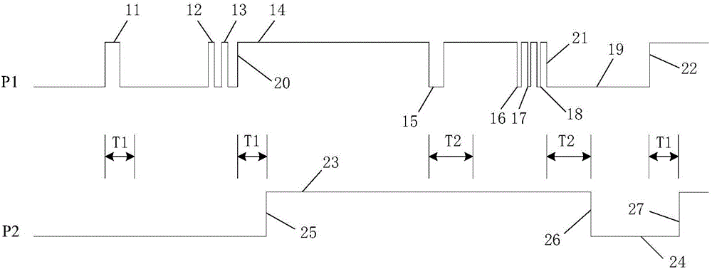
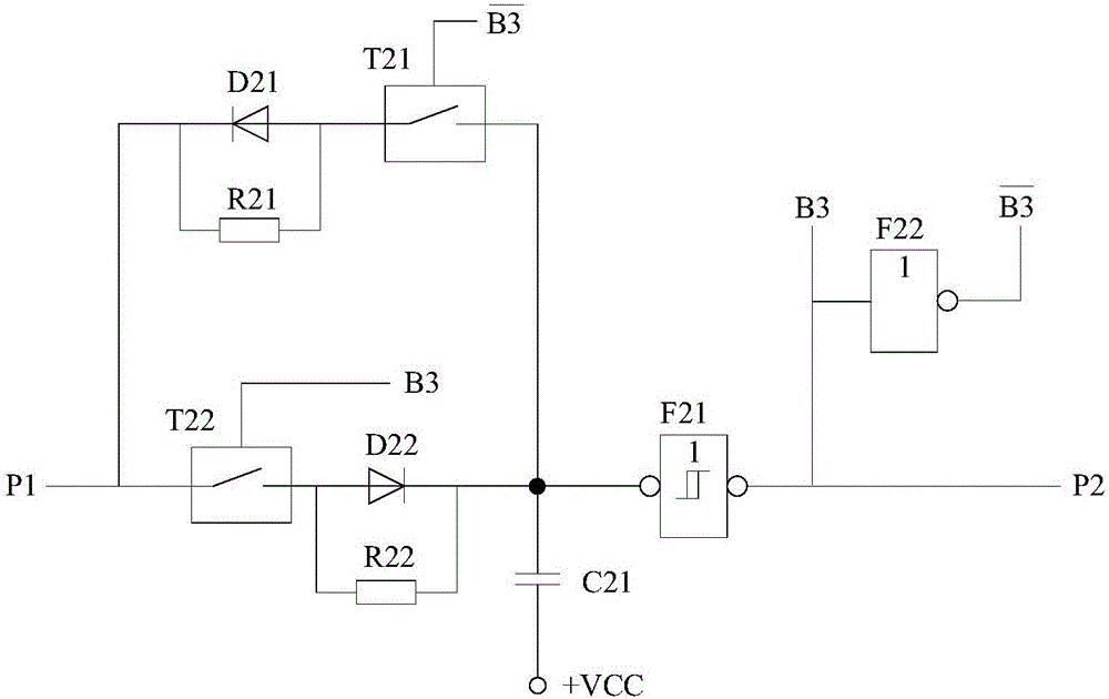
A locomotive speed sensor signal filtering device comprises an input pulse generating circuit, a quick discharging circuit, a quick charging circuit, a capacitor and a Schmidt circuit. The quick discharging circuit and quick charging circuit are controlled by output pulses of the locomotive speed sensor signal filtering device through an analog switch or a multi-channel analog switch, one way of output pulses is selected to discharge or charge the capacitor, and signals on the capacitor are converted into output pulses through the Schmidt circuit. The locomotive speed sensor signal filtering device can automatically filter positive narrow pulses in a negative narrow pulse period and negative narrow pulse interferences in a positive wide pulse period, especially can filter continuous narrow pulse interference signals, and the maximum widths of the positive narrow pulses and negative narrow pulses needed to be filtered can be respectively adjusted by changing a charging time constant and a discharging time constant. The locomotive speed sensor signal filtering device can be applied to the occasion of locomotive speed detection or traction motor rotation speed detection.

Description

technical field [0001] The invention relates to a sensing and detecting device for a rail transit vehicle, in particular to a signal filtering device for a speed sensor of a locomotive. Background technique [0002] The commonly used method for detecting the speed of the traction motor of a locomotive is to install a speed measuring gear on the small gear of the traction motor. There is a gap between the speed measuring gear and the speed sensor. An alternating frequency signal proportional to the wheel speed is generated. The shaft of the traction motor is connected to the wheel through the pinion gear and the bull gear. The sensor outputs a certain number of pulses every time the wheel rotates, so the frequency of the induced alternating signal is proportional to the speed of the traction motor of the locomotive. Due to the influence of line conditions, vibration, electromagnetic interference, sensor fixed state and other factors, the speed signal is often mixed with some...

Claims


Application Information

Patent Timeline
IPC IPC(8): G08C25/00
CPCG08C25/00
Inventor 凌云曾红兵肖会芹
Owner 邳州市景鹏创业投资有限公司
Learn More