Low-fluctuation asymmetric type permanent magnetic rotor for electric vehicle motor

A technology for electric vehicles and permanent magnet rotors, applied in electric components, magnetic circuits, electrical components, etc., can solve the problems of reducing the area of ​​the stator slot, increasing the manufacturing cost of the motor, and reducing the output, so as to reduce the core loss and torque fluctuation. , The effect of reducing mechanical vibration

Inactive Publication Date: 2016-08-17
SHANGHAI TOP MOTOR
View PDF7 Cites 2 Cited by
  • Summary
  • Abstract
  • Description
  • Claims
  • Application Information

AI Technical Summary

Problems solved by technology

Existing methods for reducing motor torque fluctuation mainly include fractional slot method, auxiliary slot method, auxiliary tooth method, inclined slot method, oblique pole method, closed slot method, and magnetized slot wedge method. These methods have their own advantages and disadvantages, but they are always difficult. Effectively eliminate the cogging effect
Inclined slots or inclined poles are the most commonly used methods to reduce torque fluctuations, but the inclined slots and inclined poles have an impact on the flat-top width of the square wave motor’s air-gap magnetic induction intensity. At the same time, the stator inclined slots complicate the production process and structure, making the stator slot area Decrease, reduce output, increase copper consumption, both chute and oblique pole reduce output, complicate the process and structure of the motor, and increase the manufacturing cost of the motor

Method used


Image

  • Low-fluctuation asymmetric type permanent magnetic rotor for electric vehicle motor
  • Low-fluctuation asymmetric type permanent magnetic rotor for electric vehicle motor
  • Low-fluctuation asymmetric type permanent magnetic rotor for electric vehicle motor

Examples


Embodiment Construction

[0023] The embodiments of the present invention are described in further detail below in conjunction with the accompanying drawings, but the present embodiments are not intended to limit the present invention. All similar structures and similar changes of the present invention should be included in the scope of protection of the present invention. The commas in all indicate the relationship between and.

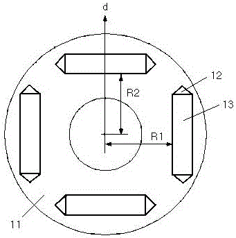
[0024] like figure 1 As shown, in the low-fluctuation asymmetric permanent magnet rotor of an electric vehicle motor provided by the first embodiment of the present invention, a plurality of inline permanent magnet slots 12 are opened on the rotor 11, and each inline permanent magnet There is a font magnetic steel 13 embedded in the groove, which is characterized in that:

[0025] Each inline permanent magnet slot 12 is equally divided into two categories, one of which is a class A permanent magnet slot, and the other is a class B permanent magnet slot, and each class A perm...


PUM


Abstract

The invention relates to the technical field of motors, in particular to a low-fluctuation asymmetric type permanent magnetic rotor for an electric vehicle motor. The low-fluctuation asymmetric type permanent magnetic rotor solves the technical problem of difficulty in reducing motor moment fluctuation. A plurality of slotted permanent magnetic grooves are formed in the rotor, wherein a piece of slotted magnetic steel is embedded into each slotted permanent magnetic groove, the slotted permanent magnetic grooves are divided into a type A and a type B, the type A permanent magnetic grooves and the type B permanent magnetic grooves are alternatively distributed in the circumferential direction of the rotor, the radial inserting depths of the A type permanent magnetic grooves are the same, the radial inserting depths of the B type permanent magnetic grooves are the same, the radial inserting depths of the A type permanent magnetic grooves are larger than the radial inserting depths of the B type permanent magnetic grooves, and the radial inserting depths of the slotted permanent magnetic grooves are the minimum distance between the slotted permanent magnetic grooves and the axis of the rotor. The rotor is especially suitable for an electric vehicle.

Description

technical field [0001] The invention relates to motor technology, in particular to the technology of a low-fluctuation asymmetric permanent magnet rotor of an electric vehicle motor. Background technique [0002] Electric vehicles are an important way to solve energy crisis and environmental pollution. The driving motor for electric vehicles restricts the research and development and industrialization process of electric vehicles in China. Especially in the high-efficiency built-in permanent magnet synchronous motor suitable for electric vehicles, there are defects such as low power density, narrow high-speed constant power range, large torque fluctuation, low overload capacity and poor reliability, which make it difficult to meet the requirements. The driving motor for electric vehicles restricts the research and development and industrialization process of electric vehicles in China. [0003] Cogging torque (also known as reluctance torque) is a fatal defect in the speed...

Claims


Application Information

Patent Timeline
Patent Type & Authority Applications(China)
IPC IPC(8): H02K1/27
CPCH02K1/276
Inventor 林德芳
Owner SHANGHAI TOP MOTOR
Why Eureka
Try Eureka