
Power source control device capable of dynamically adjusting driving ability

A technology of power control device and driving capability, which is applied in the direction of output power conversion device, energy industry, electrical components, etc., which can solve the problems of inability to reduce electromagnetic interference, increase the adverse effects of EMI, and large conduction current at the same time, so as to improve EMI effect, reduce switching loss, and improve efficiency

Inactive Publication Date: 2016-08-17
产晶积体电路股份有限公司
View PDF4 Cites 6 Cited by
  • Summary
  • Abstract
  • Description
  • Claims
  • Application Information

AI Technical Summary

Problems solved by technology

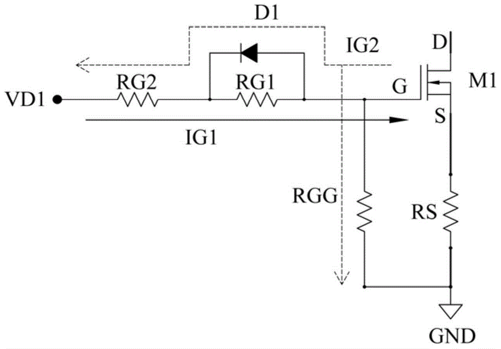
However, the disadvantage of the prior art is that only different first gate resistors RG1 and second gate resistors RG2 can be configured to change the turn-on time and turn-off time of the switching transistor M1 by the driving signal VD1. Although the switching loss can be moderately reduced, However, electromagnetic interference cannot be reduced at the same time
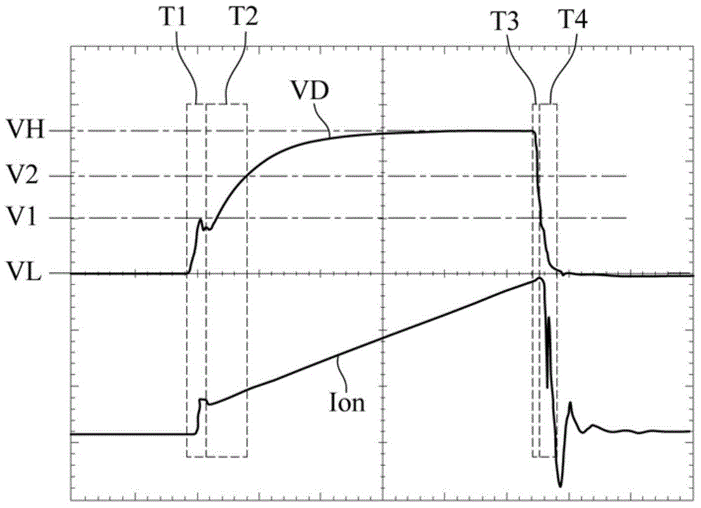
That is, when the switching transistor needs to be turned on, the conduction current in the original off state is 0 or close to 0, so if the driving voltage rises rapidly at this time, it is not helpful to reduce the switching loss, but instead Will increase the adverse effects of EMI
On the other hand, when the switching transistor is partially turned on or fully turned on, the conduction current is quite large. At this time, if the driving voltage rises or falls slowly, it will cause a lot of power in the whole switching process. loss

Method used


Image

  • Power source control device capable of dynamically adjusting driving ability
  • Power source control device capable of dynamically adjusting driving ability
  • Power source control device capable of dynamically adjusting driving ability

Examples


Embodiment Construction

[0096] The embodiments of the present invention will be described in more detail below with reference to the drawings and reference numerals, so that those skilled in the art can implement them after studying this specification.

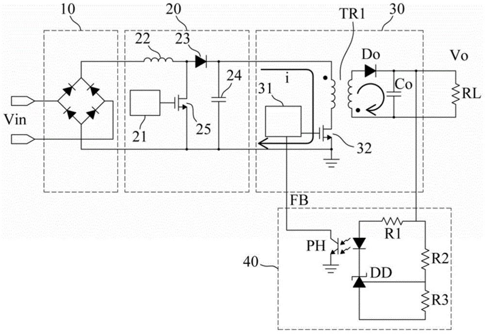
[0097] refer to figure 2 , is a schematic diagram of a power control device for dynamic driving capability adjustment according to the first embodiment of the present invention. Such as figure 2 As shown, the power supply control device for dynamic driving capability adjustment in the first embodiment essentially includes a rectification unit 10, a power factor correction unit 20, a power conversion unit 30, and a feedback unit 40 for converting an AC input power supply with an input voltage Vin to It is converted into an output power supply with an output voltage Vo, and provides output power to an external load RL.

[0098] Specifically, the rectifying unit 10 receives AC input power, rectifies it into DC power and transmits it to the power fac...


PUM


Abstract

The invention relates to a power source control device capable of dynamically adjusting driving ability. The power source control device comprises a rectifying unit, a power factor correction unit, a power source conversion unit and a feedback unit; the rectifying unit receives an alternating current input power source, rectifies the alternating current input power source to obtain a direct current power source, and transmits the direct current power source to the power factor correction unit for performing power factor correction processing on the direct current power source; a generated power factor corrected power source is transmitted to the power source conversion unit; the feedback unit is electrically connected with the power source conversion unit, so that a control loop can be formed; and the pulse width modulation driving controller of the power source conversion unit carries out adjustment processing according to the feedback signals of the feedback unit so as to control a switching transistor, so that the power factor corrected power source can be converted into an output power source which is provided for an external load. With the power source control device of the invention adopted, the optimal on current of the switching transistor can be realized, and electromagnetic interference margin can be increased, and switching loss can be reduced.

Description

technical field [0001] The present invention relates to a power control device for dynamic drive capability adjustment, especially for forward (Forward) architecture, full-bridge power conversion architecture, half-bridge power conversion architecture, boost (Boost) power conversion architecture, step-down ( The power conversion unit of the Buck) power conversion architecture can dynamically adjust the generated pulse width modulation drive signal according to the state of the switching transistor and consider the electromagnetic interference (EMI) and switching loss by performing adjustment processing to achieve dynamic The purpose of adjusting the driving capability of the switching transistor and improving the electrical quality and the overall source conversion efficiency. Background technique [0002] Power conversion technology is very important to the booming electronics industry, because different electronic products require different voltages or currents to operate....

Claims


Application Information

Patent Timeline
IPC IPC(8): H02M7/217
CPCY02P80/10
Inventor 林树嘉林敬渊林志峰谢文岳
Owner 产晶积体电路股份有限公司
Learn More