Downsampling phase locked loop for preventing in-band noise from being amplified to square times of frequency dividing ratio

A frequency division ratio, phase-locked loop technology, applied in the direction of automatic power control, electrical components, etc., can solve the problem of enlarging the frequency division ratio square times, and achieve the effect of less design difficulty

Inactive Publication Date: 2016-08-17
NO 24 RES INST OF CETC
View PDF4 Cites 18 Cited by
  • Summary
  • Abstract
  • Description
  • Claims
  • Application Information

AI Technical Summary

Problems solved by technology

The phase-locked loop is characterized by a simple structure and a stable loop, but its disadvantages: due to the existence of the frequency divider in the loop, the noise from the phase detector / charge pump and the frequency divider (also known as in-band noise) When passed to the output of the phase-locked loop, it will be enlarged by the square of the frequency division ratio

Method used


Image

  • Downsampling phase locked loop for preventing in-band noise from being amplified to square times of frequency dividing ratio
  • Downsampling phase locked loop for preventing in-band noise from being amplified to square times of frequency dividing ratio
  • Downsampling phase locked loop for preventing in-band noise from being amplified to square times of frequency dividing ratio

Examples


Embodiment Construction

[0039] The preferred embodiments of the present invention will be described in detail below in conjunction with the accompanying drawings; it should be understood that the preferred embodiments are only for illustrating the present invention, rather than limiting the protection scope of the present invention.

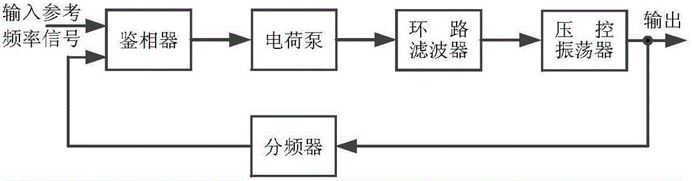
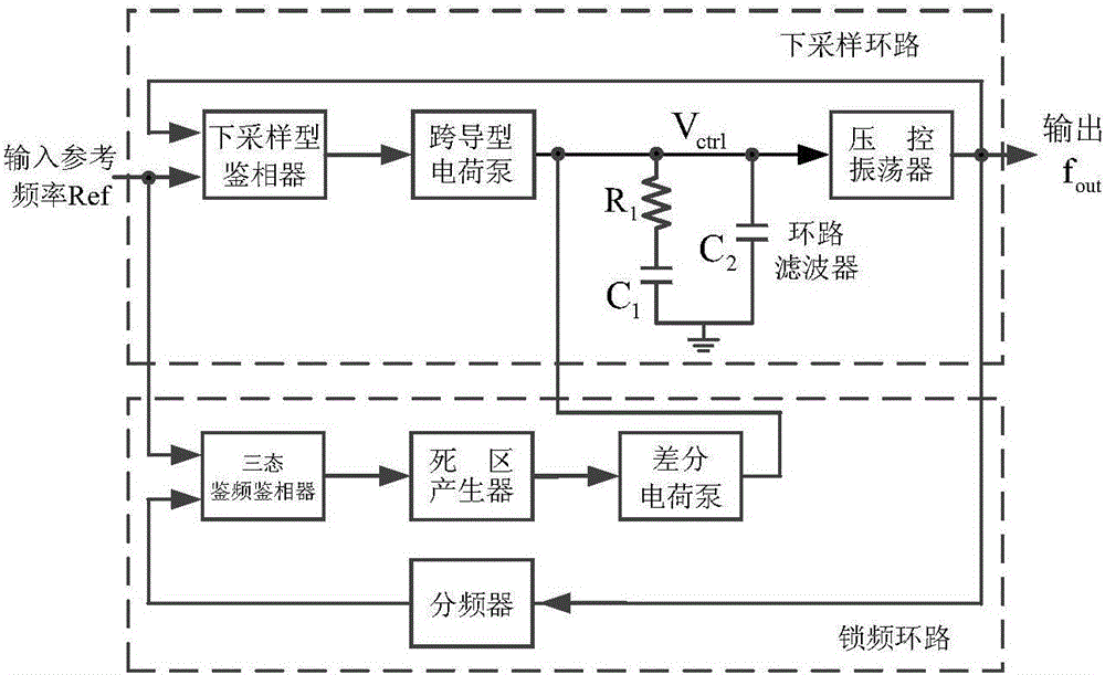
[0040] A down-sampling phase-locked loop structure that prevents in-band noise from being amplified to the square of the frequency division ratio. It is directly applied to clock generation circuits based on phase-locked loops in analog integrated circuits, especially for high frequency and low Phase noise clock generation, which includes downsampling loop and frequency-locked loop. The frequency-locked loop is responsible for reducing the difference between the product of the reference frequency and the frequency division ratio and the output frequency of the voltage-controlled oscillator. When this If the difference is small enough, the frequency-locked loop stops work...


PUM


Abstract

The invention discloses a down-sampling phase-locked loop that prevents in-band noise from being amplified to the square of the frequency division ratio. Down-sampling phase detector, transconductance charge pump, loop filter, and voltage-controlled oscillator; frequency-locked loop, including, three-state frequency detector, dead-zone generator, differential charge pump, and frequency converter. When the down-sampling phase-locked loop circuit of the present invention is locked, the frequency-locked loop does not work, and the down-sampling loop does not contain a frequency divider, so from the reference frequency signal, the frequency and phase detector and the charge pump The noise of the phase-locked loop will not be amplified to the square of the frequency division ratio at the output of the phase-locked loop. It can be widely used in clock generation circuits based on phase-locked loops in analog integrated circuits, especially clock generation with high frequency and low phase noise. .

Description

technical field [0001] The invention relates to a phase-locked loop structure, in particular to a down-sampling type phase-locked loop structure which prevents in-band noise from being amplified to the square times of the frequency division ratio. Background technique [0002] The phase-locked loop circuit is the core unit circuit of the analog integrated circuit, especially in the clock generation circuit with high frequency and low phase noise, the phase-locked loop determines the performance index of the clock generation circuit. At present, there are various loop structures of phase-locked loops, including charge-pump phase-locked loops, self-bias phase-locked loops, multi-loop phase-locked loops, etc. There are fewer phase-locked loops that use down-sampling loop structures. figure 1 It is the loop structure of the traditional charge-pump phase-locked loop. The main building blocks include a three-state frequency and phase detector, a charge pump, a loop filter, a volt...

Claims


Application Information

Patent Timeline
Patent Type & Authority Applications(China)
IPC IPC(8): H03L7/085H03L7/091H03L7/107H03L7/18
CPCH03L7/085H03L7/091H03L7/107H03L7/18
Inventor 季瑾月张瑞涛蒲杰丁一陈刚
Owner NO 24 RES INST OF CETC
Why Eureka
Try Eureka