Equipment for efficiently machining flange

A processing equipment and high-efficiency technology, applied in metal processing equipment, flange connection, mechanical equipment, etc., can solve the problems of low processing accuracy, poor effect, complex structure, etc., to improve processing efficiency, good coordination effect, and high degree of automation Effect

Inactive Publication Date: 2016-08-24
安徽奇祥汽车零部件有限公司
View PDF0 Cites 12 Cited by
  • Summary
  • Abstract
  • Description
  • Claims
  • Application Information

AI Technical Summary

Problems solved by technology

[0003] The existing device for flange processing has complex structure, low processing accuracy and poor effect, and needs further improvement

Method used


Image

  • Equipment for efficiently machining flange

Examples


Embodiment Construction

[0033] It should be noted that, in the case of no conflict, the embodiments in the present application and the features in the embodiments can be combined with each other; the present invention will be described in detail below with reference to the accompanying drawings and in combination with the embodiments.

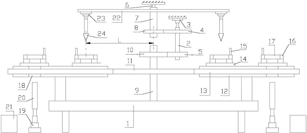
[0034] refer to figure 1 :

[0035] A high-efficiency processing equipment for flanges proposed by the present invention includes a console 1, a rotating shaft 2, a first power unit 3, a first runner 4, a second runner 5, a bracket 6, a support shaft 7, a second A gear 8, a processing mechanism, an installation shaft 9, a second gear 10, a third gear 11, and N clamping mechanisms, where N≥2, and N is a positive integer.

[0036] The rotating shaft 2 is placed above the console 1, and the rotating shaft 2 is arranged vertically.

[0037] The first power unit 3 is used to drive the rotating shaft 2 to rotate.

[0038] The first runner 4 and the second runner 5 are su...


PUM


Abstract

The invention discloses equipment for efficiently machining a flange. The equipment comprises an operating floor, a rotating shaft, a first power unit, a first rotating wheel, a second rotating wheel, a support, a supporting shaft, a first gear, a machining mechanism, a mounting shaft, a second gear, a third gear and N clamping mechanisms, wherein N is greater than or equal to 2 and is a positive integer; the rotating shaft is placed above the operating floor and is arranged in the vertical direction; the first power unit is used for driving the rotating shaft to rotate; the first rotating wheel and the second rotating wheel are successively mounted on the rotating shaft from top to bottom; a section of first wheel teeth is arranged on the outer peripheral surface of the first rotating wheel; M sections of second wheel teeth are arranged on the outer peripheral surface of the second rotating wheel, and M is greater than or equal to 2 and is a positive integer; and the supporting shaft is placed above the operating floor, is arranged in the vertical direction, is placed on one side of the rotating shaft, and is rotatably mounted on the support. The equipment for efficiently machining the flange is good in machining effect.

Description

technical field [0001] The invention relates to the technical field of flange processing, in particular to a high-efficiency processing equipment for flanges. Background technique [0002] Flanges are also called flanges or flanges. Flanges are parts that connect pipes to pipes and are connected to pipe ends. Flange connection or flange joint refers to the detachable connection of flange, gasket and bolt as a group of combined sealing structure. Pipe flange refers to the flange used for piping in pipeline installations. Upper refers to the inlet and outlet flanges of the equipment. There are holes in the flange, and the bolts make the two flanges tightly connected; the flanges are sealed with gaskets; the flanges are divided into threaded flanges and welding flanges. [0003] The existing device for flange processing has complex structure, low processing precision and poor effect, and needs further improvement. Contents of the invention [0004] In order to solve the te...

Claims


Application Information

Patent Timeline
Patent Type & Authority Applications(China)
IPC IPC(8): B23B39/16B23Q1/01B23Q3/06B23Q5/04F16L23/02
CPCB23B39/162B23Q1/015B23Q3/06B23Q5/04B23Q2220/004F16L23/02
Inventor 范建强舒晓雪陆斌
Owner 安徽奇祥汽车零部件有限公司
Why Eureka
Try Eureka