Wrapped type pipe manufacturing mold core assembly

A core component and wrapping technology, which is applied in the field of wrapping tube-making core components, can solve the problems of low production efficiency and difficult to unify quality standards, and achieve the effect of high molding quality

Inactive Publication Date: 2016-08-24
福建首聪世豪实业有限公司
6 Cites 0 Cited by

AI-Extracted Technical Summary

Problems solved by technology

[0002] At present, pipes (flue pipes or exhaust pipes) are usually made of artificial ...

Method used

[0025] The spraying assembly 2 is to spray the outer periphery of the tubular formwork formed by the wrapping layer 14. When the wrapping layer 14 adopts disposable materials, the wrapping layer 14 does not need to be recycled, which sav...

Abstract

The invention relates to a wrapped type pipe manufacturing mold core assembly. The wrapped type pipe manufacturing mold core assembly comprises two end molds, two or more upright rods, one or more telescopic mechanisms and a wrapping layer, wherein the two end molds are coaxially arranged in a spaced mode; the upright rods are inserted on the inner sides of the two end molds and parallel to the center axes of the end molds; the telescopic mechanisms are used for unfolding the upright rods with the center axes of the end molds being centers towards the outer sides; and the wrapping layer is wrapped on the part, between the two end molds, of the peripheries of the upright rods and forms a continuous pipe-shaped structure. The provided wrapped type pipe manufacturing mold core assembly is convenient to demold and reusable. The wrapped type pipe manufacturing mold core assembly has the advantages that materials are sprayed on the vertical surfaces of a pipe-shaped mold plate formed by the wrapping layer through the spraying assembly, forming of a pipe body can be completed rapidly, and the forming quality is high; moreover, after the pipe body is solidified, the mold core assembly can be taken out by being contracted, and repeated utilization is achieved; and in addition, the wrapping layer can be made of disposable materials and do not need to be recycled, and time and effort are saved.

Application Domain

Technology Topic

Image

  • Wrapped type pipe manufacturing mold core assembly
  • Wrapped type pipe manufacturing mold core assembly
  • Wrapped type pipe manufacturing mold core assembly

Examples

  • Experimental program(1)

Example Embodiment

[0018] The content of the present invention will be described in detail below in conjunction with the accompanying drawings and embodiments of the description:
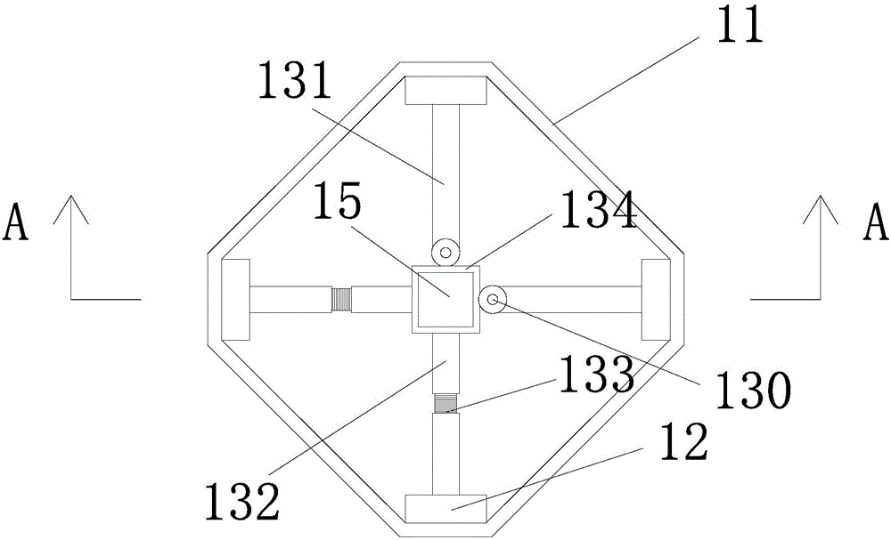
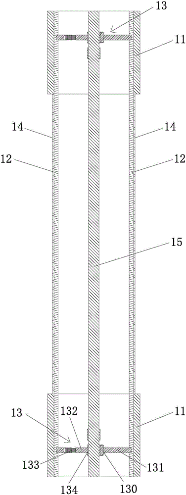
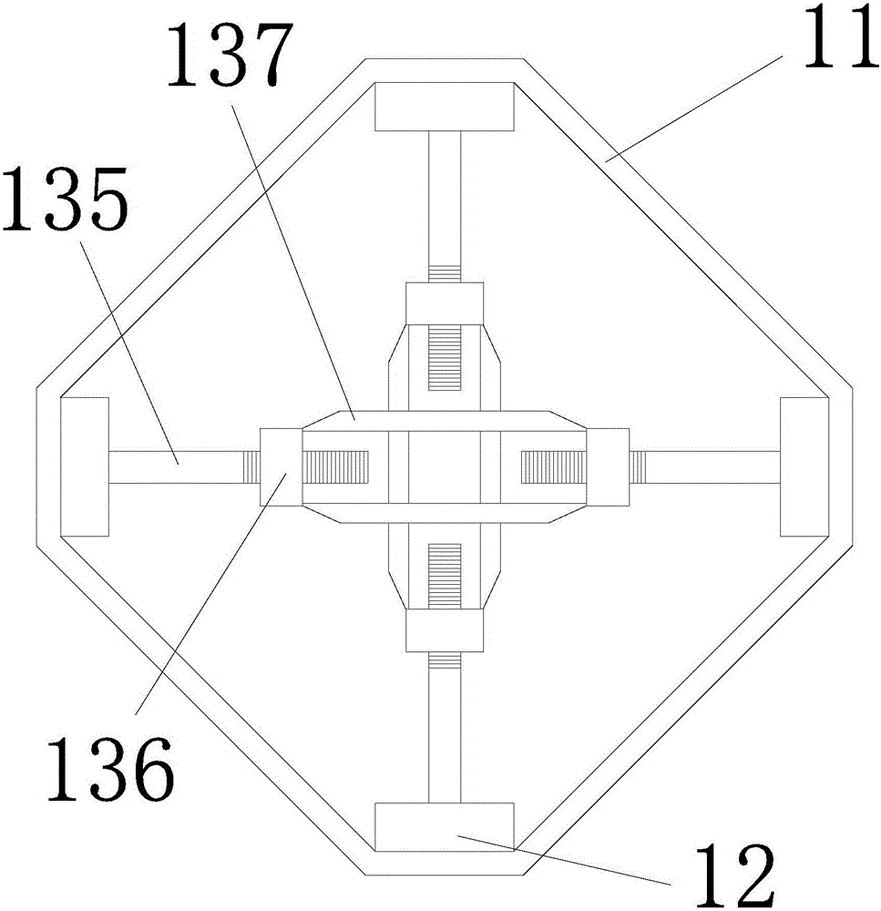
[0019] like Figure 1 to Figure 10 Shown is a schematic diagram of an embodiment of a wrap-type tube-making mold core assembly provided by the present invention.
[0020] A wrap-type pipe-making mold core assembly, which comprises two coaxially spaced end head molds 11, two or more vertical rods 12 inserted inside the end head molds 11 and parallel to the central axis of the end head molds 11, One or more telescopic mechanisms 13 for expanding each vertical rod 12 to the outside with the central axis of the end die 11 as the center, and a wrapping layer 14 surrounding the outer circumference of the vertical rod 12 between the end die 11 and forming a continuous tubular structure , the number and shape of the vertical rods 12 are matched and set according to the cross-sectional shape of the inner cavity of the tube.
[0021] If the inner cavity of the tube (the inner cavity of the end die 11 matches the inner cavity of the tube) has a rectangular section, and the four corners of the rectangle are chamfered, the number of vertical rods 12 is four, and each One side of the root rod 12 (that is, the side that matches the oblique chamfer) is in contact with the inner side of the end die 11;
[0022] If the section of the inner cavity of the tube is an equilateral triangle, the number of vertical rods 12 is three, and the section of each vertical rod 12 is a equilateral triangle, and one corner of the equilateral triangle fits the inner side of the end die;
[0023] If the cross-section of the inner cavity of the tube is circular, the number of upright rods 12 is two or more, and the cross-section of each upright rod 12 has an arc of a circular inner cavity, and the radian edge of each upright rod 12 is connected to the end die 11 the inside of the .
[0024] The wrapping layer 14 is made of film material, paper material, cloth or tin-aluminum material. Specifically, such as plastic film, polyethylene (PE), kraft paper, canvas, non-woven fabric, nylon, tin foil.
[0025] The spraying component 2 is to spray the outer periphery of the tubular template formed by the wrapping layer 14 . When the wrapping layer 14 is made of disposable materials, the wrapping layer 14 does not need to be recycled, which saves time and effort.
[0026] The telescopic mechanisms 13 can be divided into two groups, which are respectively arranged in the die 11 at both ends.
[0027] The telescopic mechanism 13 can be implemented in the following four ways
[0028] The first:
[0029] When the number of the vertical rods 12 is an even number, the telescopic mechanism 13 includes more than one set of spreading members laterally arranged between the opposite side vertical rods 12;
[0030] Each spreader includes a mutually hinged support leg A131 and a support leg B132, and a telescopic adjustment structure 133 for adjusting the length is provided on the support leg A131 and/or the support leg B132.
[0031] Preferably, an axis rod 15 fixedly connected to the opening pieces in the end die 11 on both sides can be arranged at the position of the central axis of the wrapped tube-making core assembly, and the opening pieces are provided with the axial rods 15 passing through. the retaining ring 134.
[0032] The axis rod 15 ensures that the end molds 11 on both sides are located at the same axial position, and the core assembly can be driven to rotate by the axis rod 15 to facilitate the winding of the wrapping layer 14 .
[0033] The telescopic mechanism 13 and the vertical rod 12 may be fixed by a plug-in structure, or a fixing claw matching the outer contour of the vertical rod 12 may be provided on the telescopic mechanism 13 .
[0034] A spring 139 is provided between the leg A131 and the leg B132.
[0035] Figure 8 Among them, the outrigger A131 is hinged with the fixing ring 134 , the outrigger B132 is fixedly connected to the fixing ring 134 , and a telescopic adjustment structure 133 is arranged on the outrigger B132 .
[0036] Figure 9 Among them, the outrigger A131 and the outrigger B132 are hinged with the fixing ring 134 respectively, and the telescopic adjustment structure 133 is provided on both the outrigger A131 and the outrigger B132.
[0037] The second:
[0038] When the number of the vertical rods 12 is an even number, the telescopic mechanism 13 includes more than one set of threaded members laterally arranged between the opposite side vertical rods 12;
[0039] Each threaded member includes two adjusting screws 135 , two fixing nuts 136 respectively matched with the adjusting screws 135 , and a connecting rod 137 connected between the two fixing nuts 136 .
[0040] The telescopic mechanism 13 and the vertical rod 12 may be fixed by a plug-in structure, or a fixing claw matching the outer contour of the vertical rod 12 may be provided on the telescopic mechanism 13 .
[0041] The third:
[0042] The telescopic mechanism 13 includes telescopic arms 138 controlled by air cylinders or hydraulic cylinders and matching the number of the vertical rods 12 . The telescopic mechanism 13 is applicable to the case where the number of the poles 12 is odd.
[0043] Preferably, an axial rod 15 fixedly connected to the telescopic mechanism 13 in the end die 11 on both sides can be arranged at the central axis of the wrapped pipe-making core assembly, and the telescopic mechanism 13 is provided with an axial rod 15 to pass through. the retaining ring 134.
[0044] The telescopic mechanism 13 and the vertical rod 12 may be fixed by a plug-in structure, or a fixing claw matching the outer contour of the vertical rod 12 may be provided on the telescopic mechanism 13 .
[0045] Fourth:
[0046] The telescopic mechanism 13 includes a shaft rod 15 disposed on the central axis of the end die 11 , a sliding block 161 sleeved on the shaft rod 15 and threadedly engaged with the shaft rod 15 , and sleeved on the shaft rod 15 . The fixing block 162 which is clearance-fitted with the shaft rod 15 and a number of folding arm pieces correspondingly matched with the vertical rods 12 respectively; 163 for positioning;
[0047] The arm member includes a support rod A164 and a support rod B165. The end of the support rod A164 and the end of the support rod B165 are hinged on the side wall of the sliding block 161 and the side wall of the fixed block 162 on the same side, respectively. The other ends of A164 and B165 are hinged to each other.
[0048] The hinged end between the support rod A164 and the support rod B165 is fixed on the inner side wall of the vertical rod 12 .
[0049] The telescopic mechanism 13 is applicable to the case where the number of the poles 12 is odd.
[0050] When the shaft rod 15 rotates, the nuts 163 on the upper and lower sides of the fixing block 162 make the height position of the fixing block 162 on the shaft rod 15 unchanged; the sliding block 161 and the shaft rod 15 are screwed together because they are folded. The arm piece is connected with the fixed block 162, so it cannot be rotated, only the shaft rod 15 can slide up and down.
[0051] like Figure 10 As shown, there are two groups of spraying assemblies 2, which are respectively arranged on the left and right sides of the wrapped pipe-making core assembly, and each spraying assembly 2 is driven by a lifting power member 4 to move up and down.
[0052] The wrapped tube-making core assembly is placed on the spraying platform 3 and is driven by the spraying platform 3 to rotate.
[0053] The wrapped pipe-making core assembly can also be matched with a spraying robot arm, and the spraying robot arm takes the wrapped pipe-making core assembly as the central axis for spiral lifting and spraying.

PUM

no PUM

Description & Claims & Application Information

We can also present the details of the Description, Claims and Application information to help users get a comprehensive understanding of the technical details of the patent, such as background art, summary of invention, brief description of drawings, description of embodiments, and other original content. On the other hand, users can also determine the specific scope of protection of the technology through the list of claims; as well as understand the changes in the life cycle of the technology with the presentation of the patent timeline. Login to view more.

Similar technology patents

Foundry molding sand processing and feeding device

InactiveCN104439050AImprove molding qualityRealization of continuous processing productionMould handling/dressing devicesEngineeringMolding sand
Owner:HEFEI RUIHONG HEAVY MACHINERY

Classification and recommendation of technical efficacy words

Why Eureka
Try Eureka