
Light-emitting pen

A luminous pen and pen tube technology, applied to writing utensils, mechanically driven clocks, instruments, etc., can solve the problems of no storage function, no time and direction identification, no luminous function, etc., and achieve the effect of simple structure

Inactive Publication Date: 2016-08-24
刘少贺
View PDF0 Cites 0 Cited by
  • Summary
  • Abstract
  • Description
  • Claims
  • Application Information

AI Technical Summary

Problems solved by technology

[0004] It has no light-emitting function, no cooling function, no storage function, no function of reading time and identifying direction

Method used


Image

  • Light-emitting pen

Examples


Embodiment Construction

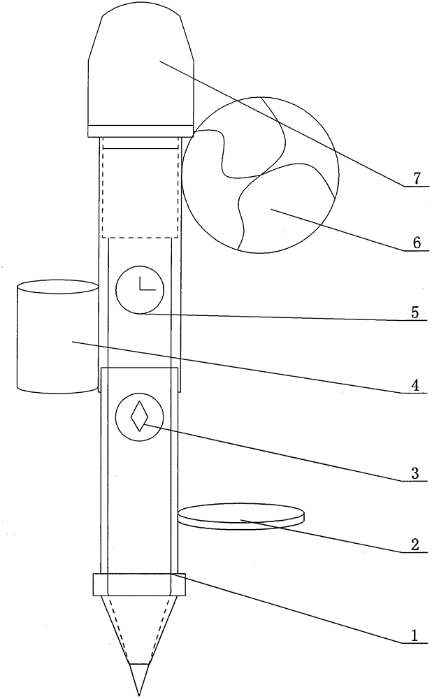
[0025] As shown in the figure, the present invention includes a pen tube 1, which is characterized in that an electronic watch 5 and a compass 3 are arranged on the pen tube 1, a storage box 4 is provided on the side of the pen tube 1, and a The magnifying glass 2 is provided with a fan 6 at the top of the side of the pen tube 1 and above the magnifying glass 2;

[0026] As a preferred solution, the pen tube 1 adopts a plastic pen tube.

[0027] As another preferred solution, the compass 3 is arranged on the lower side of the electronic watch 5 .

[0028] As yet another preferred solution, the cross-sectional shape of the pen tube 1 is oval. The oval pen barrel is more in line with the characteristics of the human hand, making it easy to hold the pen.

[0029] As yet another preferred solution, the magnifying glass 2 is arranged vertically to the pen tube 1 .

[0030] The above content is a further detailed description of the present invention in conjunction with specific p...


PUM


Abstract

The invention provides a light-emitting pen and relates to an improvement of a pen structure. By means of the light-emitting pen, air blowing and cooling can be achieved, time can be watched, and the directions can be distinguished. The light-emitting pen comprises a pen tube and is characterized in that the pen tube is provided with an electronic watch and a compass; the side portion of the pen tube is provided with a storage box; a magnifying lens is arranged on the side portion of the lower portion of the pen tube; a fan is arranged on the upper portion of the side portion, above the magnifying lens, of the pen tube; and an illuminating lamp is arranged at the upper end of the pen tube, and a power source connected with the illuminating lamp is arranged in the pen tube.

Description

technical field [0001] The present invention relates to the improvement of pen structure. Background technique [0002] What are generally used now are signature pens and ballpoint pens, and pencils are often used for drawing art drafts and drawing pictures. The pen is a great invention of mankind, and it is a tool for writing or drawing. The colored solid or liquid (ink) is used to draw symbols or pictures on paper or other solid surfaces through the nib, and the hardness of the solid nib is larger than that of the writing surface to engrave symbols or pictures on the surface. [0003] At present, existing and former technologies about pens have made very effective efforts to increase the functions of pens, and many excellent technical solutions have also been designed. As announced by the State Intellectual Property Office in 2009 and declared by Li Zeyu, the Chinese patent number (ZL) is the invention of No. 200820136742, and the name is the technical solution adopted b...

Claims


Application Information

Patent Timeline
IPC IPC(8): B43K29/00B43K29/087B43K29/10
Inventor 刘少贺
Owner 刘少贺
Learn More