A wave power generation apparatus with an anchor chain automatic adjusting device

An automatic adjustment device, wave power generation technology, applied in mechanical equipment, ocean energy power generation, anchoring arrangements, etc., can solve problems such as difficulty in having commercial value, reduced output power, and difficult commercial value, and achieve the effect of eliminating adverse effects

Inactive Publication Date: 2016-08-24
陈文彬
View PDF9 Cites 8 Cited by
  • Summary
  • Abstract
  • Description
  • Claims
  • Application Information

AI Technical Summary

Problems solved by technology

[0002] At present, there are the following problems in the practical application of wave power generation equipment: the completely floating type wave power generation equipment is bulky, and the attached body is much larger than the floating body, which leads to a large increase in cost and is difficult to have commercial value; Affected by the tide, in order to be able to perform work at both high tide and low tide, it is necessary to lengthen the fixing device so that the work floating body can work normally without being affected by the tide; this also leads to a significant increase in construction costs
For example, the current popular single-point floating body wave power generation equipment in the world has a very long and large appendage, and one end sinks into the still water layer to play a damping role; The range of motion of the active floating body; moreover, the damping floating body in the static water layer is not rigidly linked with the seabed, and it still cannot be absolutely static, and it will also move up and down with the active floating body, but the range is much smaller; If the movement stroke is not large, the output power will be reduced, and because the appendage is very long and large, the cost is not low, and it is difficult to have commercial value

Method used


Image

  • A wave power generation apparatus with an anchor chain automatic adjusting device
  • A wave power generation apparatus with an anchor chain automatic adjusting device
  • A wave power generation apparatus with an anchor chain automatic adjusting device

Examples


Embodiment Construction

[0023] The present invention will be further described below in conjunction with drawings and embodiments.

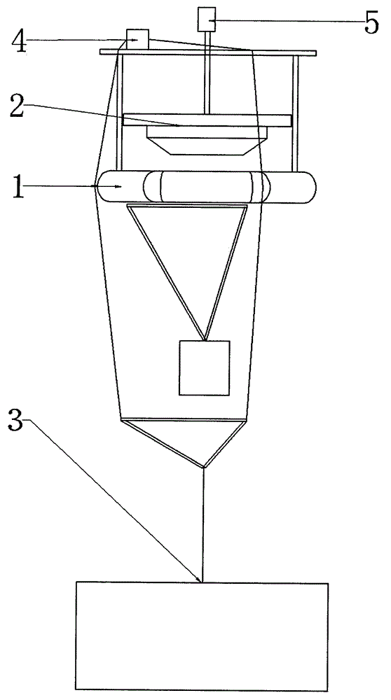
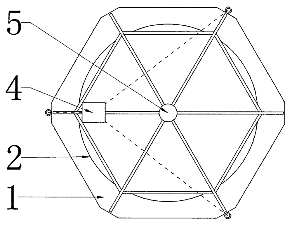
[0024] Such as figure 1 , figure 2 As shown, this embodiment is composed of an appendage system 1, a working floating body 2, an anchoring system 3, an automatic anchor chain adjustment device 4, and a power generation system 5;

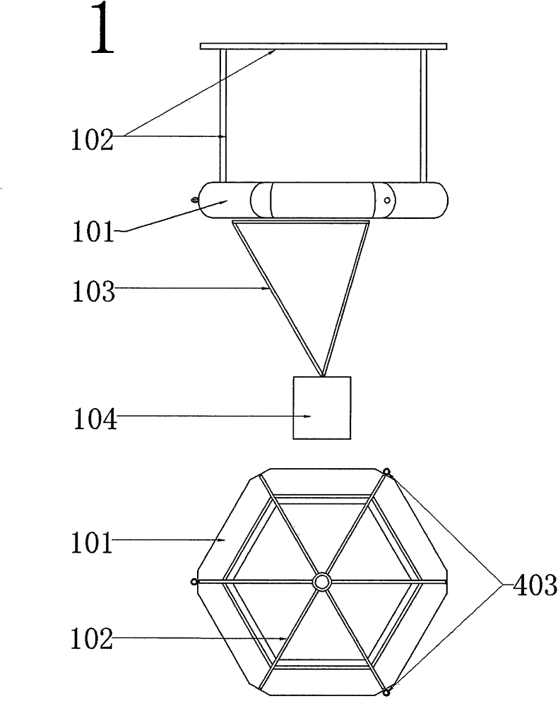
[0025] Such as image 3 , 4 As shown, the attachment system 1 is composed of an attachment floating body 101, a bracket 102, a counterweight frame 103, and a counterweight 104. The limit pulley 403 is evenly installed on the edge of the attachment floating body 101; the attachment floating body 101 is symmetrical around the axis 105 The distribution can be circular or polygonal, and this article marks a regular hexagonal cylinder; the function of the counterweight 104 is to lower the overall center of gravity and prevent the appendage system 1 from falling due to top-heavy; the axis 105 is the appendage system 1 and the central point of t...


PUM


Abstract

The invention provides a wave power generation apparatus with an anchor chain automatic adjusting device. The wave power generation apparatus is low in construction cost. The wave power generation apparatus comprises an appendage system, an acting floating box, an anchoring system, an anchor chain automatic adjusting device and a power generation system 5. The appendage system 1 is pulled by the anchoring system 3 and can be pulled in the water; when the buoyancy force and the pull force of an anchor chain reach balance, the appendage system 1 becomes motionless in water and does not rise and fall along with waves. The power generation system 5 installed on the appendage system 1 generates electric energy because a rack or a hydraulic rod thereof moves along with the acting floating body 2. The anchor chain automatic adjusting device 4 can adjust the length of a mooring rope according to the change of tides, so that the floating bodies of the appendage system 1 can be kept at a certain position under the water surface and almost maintain a stable distance with the water surface and the acting floating body 2 can move in a certain fixed range of a support. The apparatus is relatively low in construction cost, simple to manufacture, easy to install, convenient to maintain and higher in commercial value.

Description

technical field [0001] The invention relates to a device for adjusting wave power generation equipment to adapt to tidal range, in particular to an anchor chain automatic adjustment device that enables wave power generation equipment to work at low tide and to be equally efficient at high tide. technical background [0002] At present, there are the following problems in the practical application of wave power generation equipment: the completely floating type wave power generation equipment is bulky, and the attached body is much larger than the floating body, which leads to a large increase in cost and is difficult to have commercial value; Affected by the tide, in order to be able to perform work at both high tide and low tide, the fixing device must be lengthened, so that the work floating body can work normally without being affected by the tide; this also leads to a substantial increase in construction costs. For example, the current popular single-point floating body ...

Claims


Application Information

Patent Timeline
Patent Type & Authority Applications(China)
IPC IPC(8): B63B21/50B63B21/04F03B13/14
CPCY02E10/30
Inventor 陈文彬
Owner 陈文彬
Why Eureka
Try Eureka