
Creel

A yarn creel and yarn bobbin technology is applied in the field of webbing manufacturing, which can solve the problems of time-consuming, yarn winding and knotting, and increase the chance of error, and achieve the effect of saving space.

Inactive Publication Date: 2016-08-24
OPPERMANN WEBBING KUSN
View PDF9 Cites 4 Cited by
  • Summary
  • Abstract
  • Description
  • Claims
  • Application Information

AI Technical Summary

Problems solved by technology

When weaving on the ribbon loom in the prior art, it is necessary to continuously change the yarn on the yarn bobbin on the creel. After the yarn is changed, joints are required, which consumes a lot of time, and frequent yarn changes will increase the chance of error, and entanglement between yarns is easy to occur. Knotting phenomenon and generating excess waste

Method used


Image

  • Creel
  • Creel

Examples


Embodiment Construction

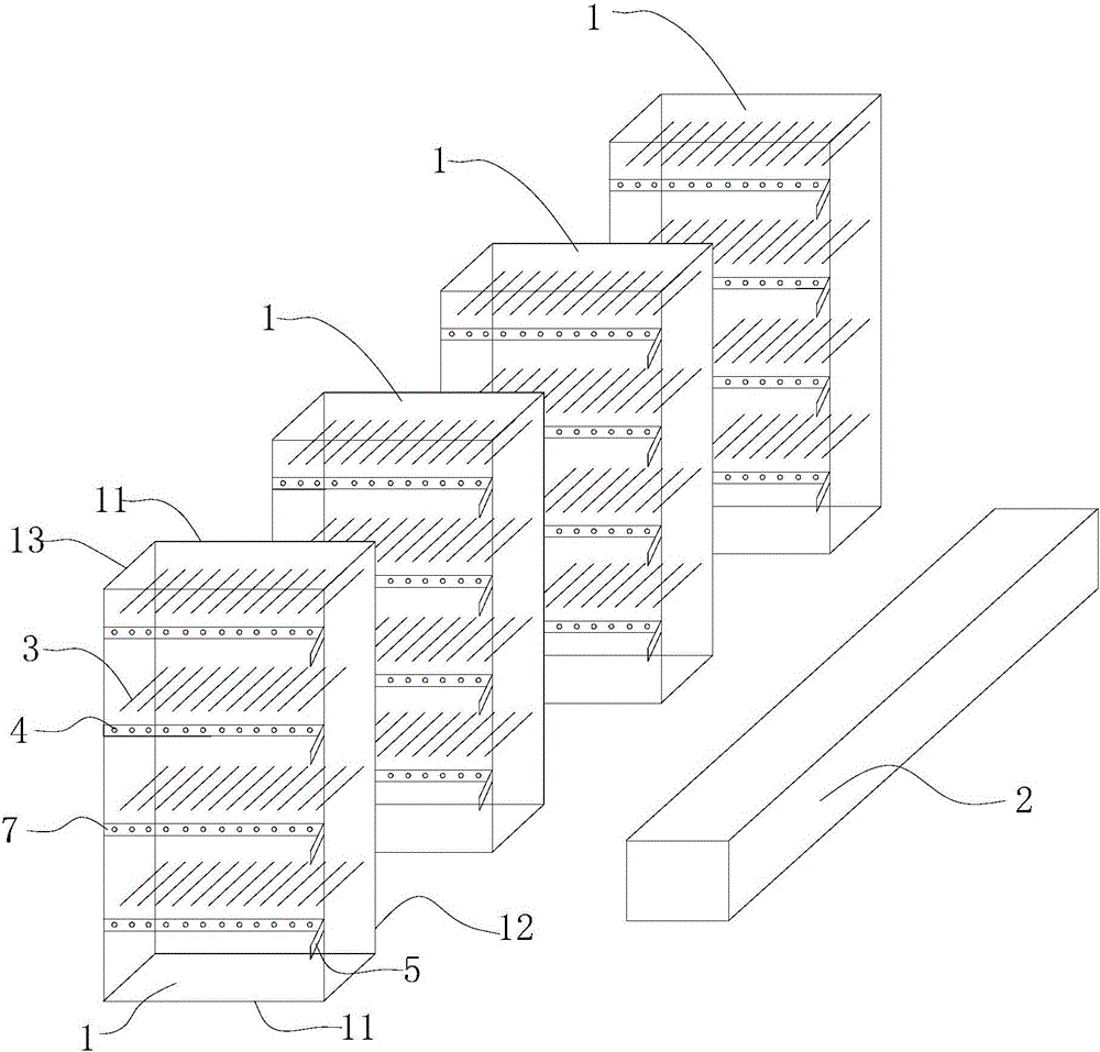
[0022] Combine below figure 1 , figure 2 The technical solutions of the present invention are further described through specific implementation methods.

[0023] It should be noted that the "front", "back", "up", and "down" mentioned in the present invention are relative to the direction of the page view, that is, the direction close to the reader is the front, and the direction away from the reader is the front. The side opposite to the front side is the rear, the direction of the upward line of sight is upward, and the direction of the downward line of sight is downward, which should not be construed as limiting the protection scope of the present invention.

[0024] like figure 1 , figure 2 As shown, a creel of the present invention includes several warp yarn creels 1 arranged side by side. All warp thread creels 1 are arranged on the same side of the textile machine 2 and are vertically placed relative to the textile machine 2. The warp thread creel 1 includes The cr...


PUM


Abstract

The invention discloses a creel. The creel comprises a plurality of warp frames. All the warp frames are arranged on the same side of a textile machine and are perpendicularly arranged relative to the textile machine. Each warp frame comprises a creel body. Each creel body comprises transverse supporting rods, longitudinal supporting rods and connection rods. A plurality of drum rods are arranged on a rear side plate of each creel body from top to bottom. A plurality of partition plates are arranged between the two longitudinal supporting rods on the front side face of each creel body. The partition plates correspond to the drum rods and parallel to the transverse supporting rods. A plurality of yarn passing holes corresponding to the drum rods are formed in the partition plates. A plurality of yarn guide plates are arranged on one longitudinal supporting rod on the front side face of each creel body. The yarn guide plates correspond to the partition plates. Yarn guide columns are arranged on the yarn guide plates. Yarn guide holes are formed in the yarn guide columns. The number of the yarn guide holes is the same as the number of the yarn passing holes. The creel is simple in structure, space is saved, more raw material yarn can be contained, and the phenomena of yarn winding and knotting are avoided.

Description

technical field [0001] The invention belongs to the technical field of ribbon manufacturing, and in particular relates to a creel. Background technique [0002] The ribbon loom is suitable for weaving various round and flat non-elastic or elastic rope belts, mainly weaving various rope belts, shoelaces, elastic belts, safety belts, decorative belts, high tension belts, fishing belts, trailer belts, sports belts and other products. The creel is an important mechanism of the ribbon loom. The creel is provided with a yarn guide plate, and the yarn guide plate is provided with a guide wire column for the yarn to pass through. When the ribbon loom works, the raw yarn is rolled into a roll and placed on the yarn barrel of the yarn creel, and the raw yarn is sent to the yarn guide plate, and is led to the textile machine for weaving after passing through the guide wire column on the yarn guide plate. When weaving on the ribbon loom in the prior art, it is necessary to continuousl...

Claims


Application Information

Patent Timeline
Patent Type & Authority Applications(China)
IPC IPC(8): B65H57/06B65H57/02
CPCB65H57/06B65H57/02
Inventor 刘晓红
Owner OPPERMANN WEBBING KUSN
Learn More