
Plate type pulsating heat pipe and manufacturing method thereof

A technology of pulsating heat pipes and manufacturing methods, which is applied in the direction of cooling/ventilation/heating transformation, indirect heat exchangers, lighting and heating equipment, etc., which can solve the problems of increasing the manufacturing cost of vapor chambers, the inability of working fluid to flow, and the capillary structure layer being easy to fall off And other issues

Inactive Publication Date: 2016-08-24
AVARY HLDG (SHENZHEN) CO LTD +1
View PDF8 Cites 2 Cited by
  • Summary
  • Abstract
  • Description
  • Claims
  • Application Information

AI Technical Summary

Problems solved by technology

However, the inner wall of the flow channel must also be provided with a capillary structure, so that the liquid working fluid can flow back to the evaporation area through capillary force to continue the gas-liquid circulation, so as to effectively achieve the effect of uniform temperature and heat dissipation, which undoubtedly greatly increases the manufacturing of the vapor chamber. cost
In addition, the capillary structure inside the vapor chamber is generally attached to the inner wall of the flow channel by such as sintering, and is not integrally formed on the inner wall of the flow channel, so the vapor chamber is easily deformed by external factors (such as collision, extrusion, etc. ), the capillary structure layer in the vapor chamber is easy to fall off, and the working fluid cannot flow, which will inevitably affect the overall heat transfer efficiency

Method used


Image

  • Plate type pulsating heat pipe and manufacturing method thereof
  • Plate type pulsating heat pipe and manufacturing method thereof
  • Plate type pulsating heat pipe and manufacturing method thereof

Examples


Embodiment Construction

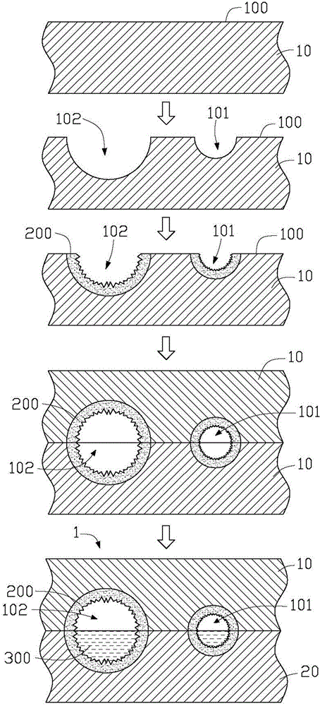
[0015] see figure 1 , the first embodiment of the present invention provides a method for manufacturing a plate-type pulsating heat pipe 1, including the following steps:

[0016] Two plate bodies 10 matching in shape are provided. The material of the plate body 10 is metal or alloy, such as magnesium-aluminum alloy, aluminum alloy, magnesium alloy, aluminum, copper and the like. In this embodiment, the board body 10 is a pure copper board. Each plate body 10 includes a flat surface 100 .

[0017] The surfaces 100 of the two boards 10 are respectively etched to form a plurality of parallel and interconnected first grooves 101 and second grooves 102 on the surfaces 100 of the two boards 10 ( figure 1 Each plate body 10 only shows one first groove 101 and one second groove 102 ). Wherein, the first groove 101 and the second groove 102 of each plate body 10 are arranged at intervals, and the width of the first groove 101 is smaller than the width of the second groove 102 . M...


PUM


Abstract

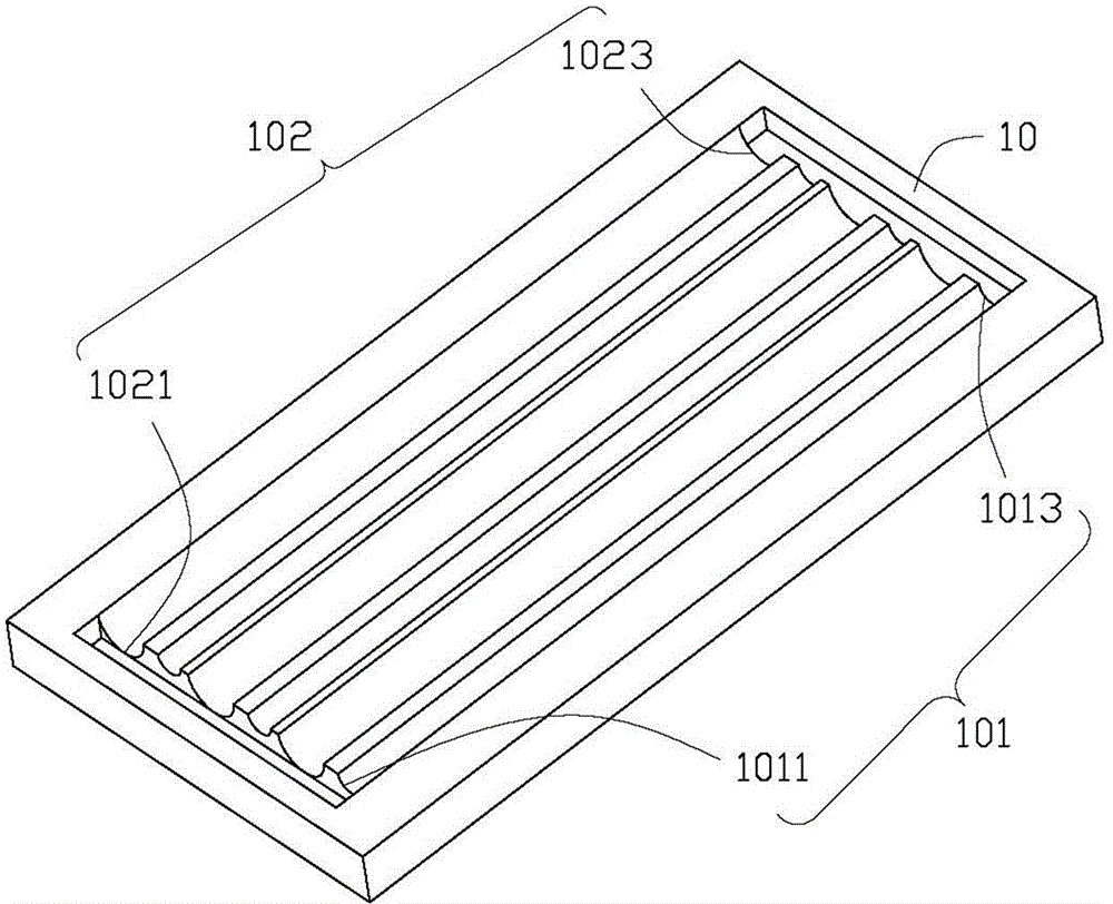
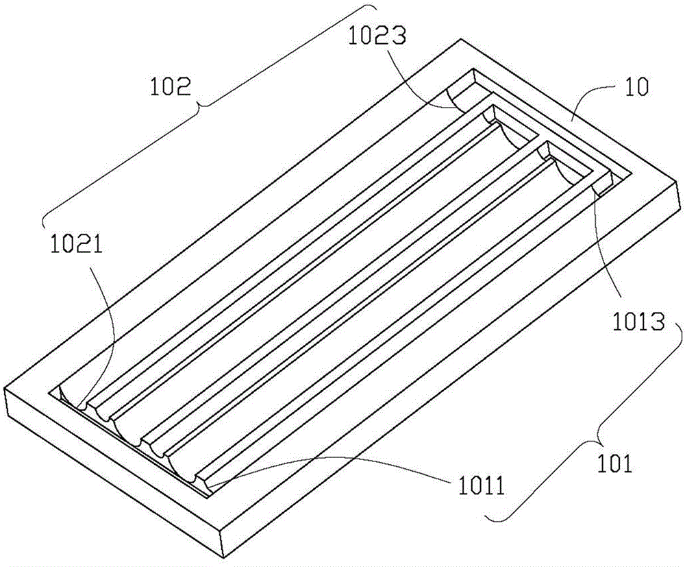
A plate type pulsating heat pipe comprises two plate bodies which are fixed oppositely. Each plate body comprises a surface. A plurality of first grooves and second grooves are formed in the surfaces of the plate bodies in parallel, and the first grooves and the corresponding second grooves communicate. The first grooves and the second grooves of each plate body are arranged alternately. The width of each first groove is smaller than that of each second groove. The first grooves and the second grooves formed in one plate body are correspondingly matched with the first grooves and the second grooves formed in the other plate body, so that flow channels are formed between the two plate bodies. The flow channels are filled with working fluid. The invention further provides a manufacturing method of the plate type pulsating heat pipe.

Description

technical field [0001] The invention relates to the field of heat dissipation, in particular to a plate-type pulsating heat pipe and a manufacturing method thereof. Background technique [0002] Among the many cooling devices, the vapor chamber, also known as flat plate heat pipe, has been widely used in central processing units, graphics display processors, high-power Radiators for electronic devices such as transistors and high-power light-emitting diodes are used to ensure that these electronic devices can operate under normal conditions without failure due to overheating. [0003] Known vapor chambers include flow channels filled with a working fluid. One side of the vapor chamber (that is, the evaporation area) is pasted on a heating element (such as a central processing unit, a graphics chip, a north-south bridge chip, and a communication chip) to absorb the heat generated by the heating element, so that the liquid working fluid is evenly distributed. The evaporation...

Claims


Application Information

Patent Timeline
Patent Type & Authority Applications(China)
IPC IPC(8): F28D15/02H05K7/20
Inventor 胡先钦沈芾云雷聪何明展
Owner AVARY HLDG (SHENZHEN) CO LTD
Learn More