
Rotational part machining precision quick and automatic measuring device and rotational part machining precision quick and automatic measuring method

A technology for parts processing and automatic measurement, which is applied in the direction of measuring devices, optical devices, instruments, etc., can solve the problems of measuring machine measurement accuracy and speed improvement limitations, simultaneous measurement, and inaccurate measurement results, etc. range, increasing overall structural rigidity, and improving collection efficiency

Inactive Publication Date: 2016-08-24
SHANDONG UNIV
View PDF17 Cites 7 Cited by
  • Summary
  • Abstract
  • Description
  • Claims
  • Application Information

AI Technical Summary

Problems solved by technology

An anti-collision mechanism of a three-coordinate measuring machine invented by Liu Binghua improves the X-direction movement mechanism (see patent number CN202033017U), but the movement errors of these moving parts in three directions make the measurement results not accurate enough, and the inside and outside of the workpiece cannot be accurately measured. Simultaneous surface measurement
Although the improved three-coordinate measuring machine (see patent No. CN204165520U) has improved the test accuracy and measurement accuracy, it uses pulleys and belts to drive the movement of the master-slave movable arm supporting the horizontal bridge, which makes the overall rigidity of the system decrease, and there is no Simultaneous measurement of the machining accuracy of the inner and outer surfaces of the workpiece is considered
[0004] The moving parts in the three-coordinate measuring machine need to rely on the guide rail slide to complete the measurement task. Using ordinary sliding guide rails or rolling guide rails, the friction resistance is relatively large, and the wear on the guide rails is serious. When the measuring machine is working at a low speed, it is easy to Leading to the occurrence of crawling phenomenon, the granite guide rail device and the three-coordinate measuring machine invented by Lin Zhiquan and others complete reciprocating motion through bearings (see patent number CN201983775U), and the Z-direction motion mechanism has a large mass, and long-term use will cause wear of the bearings. Using the long-term stable and high-efficiency work of the measuring mechanism also has certain restrictions on the improvement of the measuring accuracy and speed of the measuring machine
The measuring equipment of the traditional three-coordinate measuring machine is usually fixed on the sliding seat that moves up and down along the Z direction, but the sliding seat cannot accurately reach the designated measuring position under the action of gravity of the measuring equipment, resulting in the measurement data of the three-coordinate measuring machine distortion
The pneumatic balancing device and three-coordinate measuring machine (see patent No. CN201983771U) invented by Chen Shutao and others solved this problem to a certain extent, but due to the use of pneumatic balancing, the measurement of machining accuracy is not accurate enough
[0005] The on-line detection system and detection method of parts processing accuracy for CNC lathes invented by Deng Haiyang et al. (see patent number CN102785128A) can realize the on-line measurement of the workpiece, but it also cannot realize the simultaneous measurement of the processing accuracy of the inner and outer surfaces of the workpiece.
Although Zhou Changfeng et al. invented the three-coordinate measuring machine overturning measuring platform (see patent number CN203432563U), although it can realize the measurement of the machining accuracy of the inner and outer surfaces of the workpiece once clamped, it cannot measure the machining accuracy of the inner and outer surfaces at the same time, and the efficiency is low. There is no protection device for the process, and the floor area is increased
[0006] A measuring device that integrates a visual sensor and a three-coordinate measuring machine (see patent number CN202599371U) invented by Yang Xuerong and others uses the vision sensor to be fixed on the beam mounting plate, which cannot monitor the measuring process of the measuring machine in real time, and cannot be flexible in real time Easy orientation and position adjustments

Method used


Image

  • Rotational part machining precision quick and automatic measuring device and rotational part machining precision quick and automatic measuring method
  • Rotational part machining precision quick and automatic measuring device and rotational part machining precision quick and automatic measuring method
  • Rotational part machining precision quick and automatic measuring device and rotational part machining precision quick and automatic measuring method

Examples


Embodiment Construction

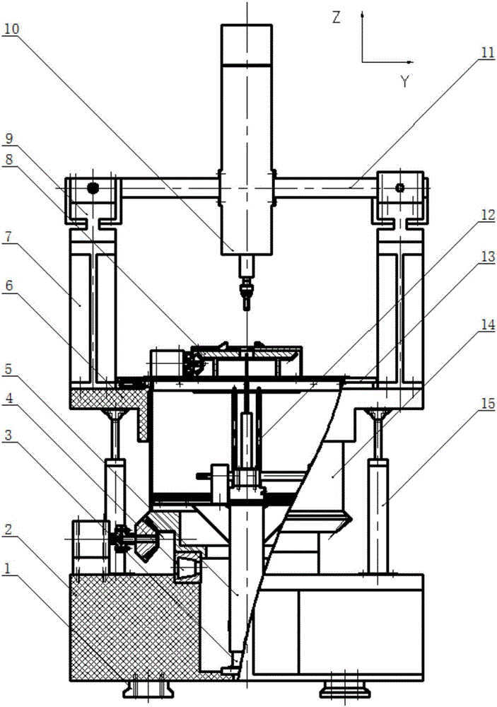
[0052] The overall structure of the rapid automatic measurement device for machining accuracy of rotary body parts in the present invention adopts a mobile bridge structure with an internal measuring frame inverted, mainly consisting of an adjustable support platform, an internal contact measurement system, an external non-contact measurement system, a safety monitoring mechanism, Control system and data storage and processing system.

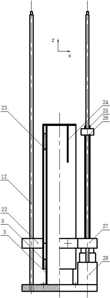
[0053] Among them: the adjustable support platform is mainly composed of a granite working platform, a perforated rotary table, a barrel-shaped rotary mechanism, a three-jaw clamping mechanism, a driving mechanism, a base, etc.;

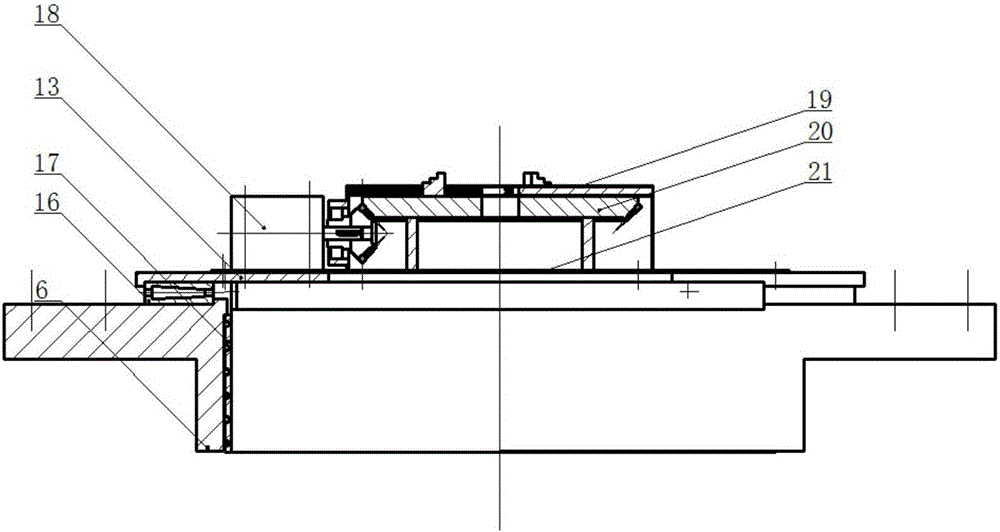
[0054] The granite work platform is connected to the base by adjustable supports, on which the stationary gantry columns are supported. The barrel slewing mechanism is mainly composed of bevel gear barrel slewing frame, perforated end cover, dense ball bearing, one-way thrust bearing, end face bearing and so on. The ...


PUM


Abstract

The invention discloses a rotational part machining precision quick and automatic measuring device and a rotational part machining precision quick and automatic measuring method. The device comprises a base, an up-down adjustable support platform is arranged on the base, and a non-contact measurement system for measuring the outer surface of a work piece is mounted on the top of the support platform. The non-contact measurement system can move along the X-axis and Z-axis directions, and can rotate about the X-axis direction. A barrel-shaped rotation mechanism for driving a work piece to rotate is mounted inside the support platform. A contact measurement system for measuring the inner surface of a work piece is mounted inside the barrel-shaped rotation mechanism. A clamping device for clamping a work piece is mounted on the top of the barrel-shaped rotation mechanism. The contact measurement system can move along the Z-axis and Y-axis directions. The contact measurement system and the non-contact measurement system are connected with a control system and a data processing system.

Description

technical field [0001] The patent of the present invention relates to the technical field of measuring instrument manufacturing and measurement, in particular to a fast and automatic measuring device and method for machining accuracy of revolving body parts. Background technique [0002] With the continuous improvement of machining precision requirements, the requirements for machining precision of rotating body parts are also getting higher and higher. Dalian University of Technology has developed a machine that can fully control the inner and outer contours of rotating body parts under the condition of one installation. A precision instrument for detecting geometric parameters and contour errors. This instrument uses sensors to achieve high-precision measurement of combined complex rotating parts (see literature: Wang Yongqing, Lin Sheng, Yu Lei, Jia Zhenyuan. Composite thin-walled rotating body Research on On-machine Measurement System of Part Taper. Journal of Dalian Uni...

Claims


Application Information

Patent Timeline
IPC IPC(8): G01B11/24
CPCG01B11/24
Inventor 唐委校刘锦宋清华王康
Owner SHANDONG UNIV
Learn More