High-frequency detection system

A detection and high-frequency technology, applied in the field of high-frequency detection systems, can solve problems such as the inability to accurately identify high-frequency signals, and achieve the effect of improving survey accuracy

Inactive Publication Date: 2016-08-24
CHENGDU NIAOER ELECTRONICS TECH CO LTD
View PDF0 Cites 2 Cited by
  • Summary
  • Abstract
  • Description
  • Claims
  • Application Information

AI Technical Summary

Problems solved by technology

[0004] The purpose of the present invention is to overcome the defect that the existing detection system cannot accurately identify high-frequency signals, and to provide a high-frequency detection system

Method used


Image

  • High-frequency detection system

Examples


Embodiment

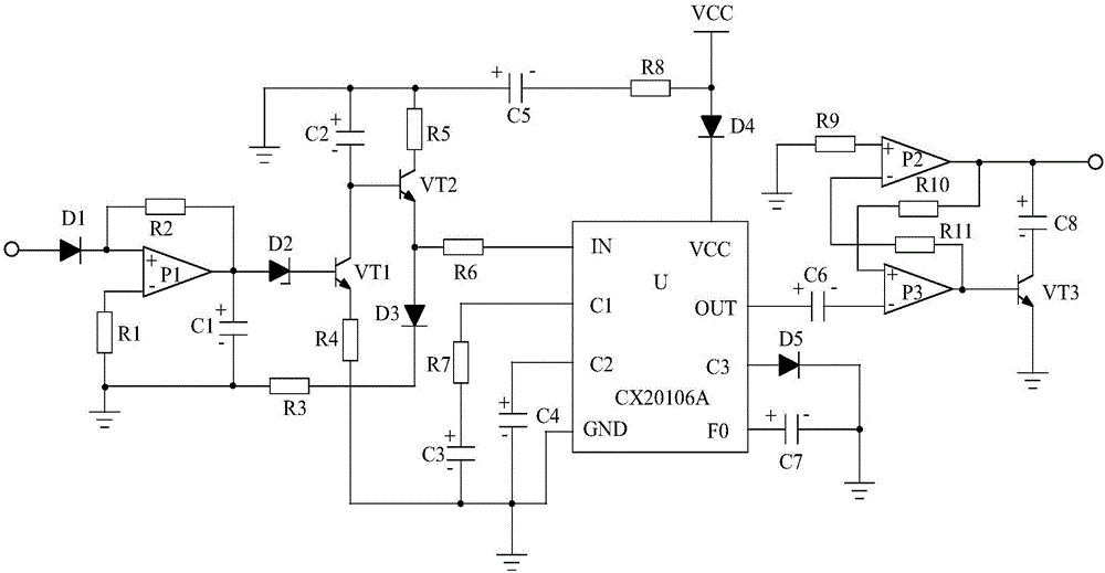
[0014] Such as figure 1 As shown, the high frequency detection system of the present invention is mainly composed of a processing chip U, a bandpass filter circuit, a resistor R6, a capacitor C5, a resistor R8, a diode D4, a resistor R7, a capacitor C3, a capacitor C4, a capacitor C7, a diode D5 and a linear Amplifying circuit composition.

[0015] Wherein, the resistor R6 is connected in series between the band-pass filter circuit and the IN pin of the processing chip U. The positive electrode of the capacitor C3 is connected to the C1 pin of the processing chip U after passing through the resistor R7, and its negative electrode is connected to the band-pass filter circuit and the GND pin of the processing chip U respectively. The positive electrode of the capacitor C4 is connected to the C2 pin of the processing chip U, and the negative electrode thereof is connected to the GND pin of the processing chip U. The P pole of the diode D5 is connected to the C3 pin of the proce...


PUM


Abstract

The invention discloses a high-frequency detection system, which is characterized by mainly comprising a processing chip U, a band pass filtering circuit, a resistor R6, a capacitor C3, a capacitor C4, a diode D5 and the like, wherein the resistor R6 is connected in series between the band pass filtering circuit and pin IN of the processing chip U; the anode of the capacitor C3 is connected with pin C1 of the processing chip U after passing through a resistor R7, and the cathode of the capacitor C3 is connected with the band pass filtering circuit and pin GND of the processing chip U; the anode of the capacitor C4 is connected with pin C2 of the processing chip U, and the cathode of the capacitor C4 is connected with pin GND of the processing chip U; electrode P of the diode D5 is connected with pin C3 of the processing chip U, and electrode N of the diode D5 is grounded. According to the high-frequency detection system, an integrated chip CX20106A can be combined with a novel peripheral circuit to effectively process an input detection signal and well identify a high-frequency signal in the detected signal, so that the high-frequency in the detected signal can be accurately identified, and the detection accuracy of a detector is greatly improved.

Description

technical field [0001] The invention relates to a wave detection system, in particular to a high-frequency wave detection system. Background technique [0002] The detector can detect some useful information in the oscillating signal. It is a device used to identify the existence or change of the oscillating signal, and can also be used to extract the information carried by the outside world. At present, geophones have been widely used in geological exploration and engineering surveys or to measure noise during equipment operation, which brings great convenience to people. [0003] However, the detection system used by the geophones currently on the market cannot accurately identify high-frequency signals, which seriously affects the exploration results of the geophones. Contents of the invention [0004] The object of the present invention is to overcome the defect that the existing detection system cannot accurately identify high-frequency signals, and provide a high-fr...

Claims


Application Information

Patent Timeline
Patent Type & Authority Applications(China)
IPC IPC(8): G01V1/18
CPCG01V1/181
Inventor 李洪军
Owner CHENGDU NIAOER ELECTRONICS TECH CO LTD
Why Eureka
Try Eureka