An Exhaust Gas Turbine Driven Electrically Excited Generator

A technology of exhaust gas turbine and electric excitation, which is used in the control of generators, combustion engines, machines/engines, etc., can solve the problem of not finding exhaust gas turbines to drive electric excitation generators, etc.

Active Publication Date: 2018-04-06
SHANDONG UNIV OF TECH
View PDF7 Cites 0 Cited by
  • Summary
  • Abstract
  • Description
  • Claims
  • Application Information

AI Technical Summary

Problems solved by technology

[0011] At present, the applicant has not retrieved any reports closely related to th

Method used


Image

  • An Exhaust Gas Turbine Driven Electrically Excited Generator
  • An Exhaust Gas Turbine Driven Electrically Excited Generator
  • An Exhaust Gas Turbine Driven Electrically Excited Generator

Examples


Embodiment Construction

[0037] The invention will be described in further detail below in conjunction with the accompanying drawings.

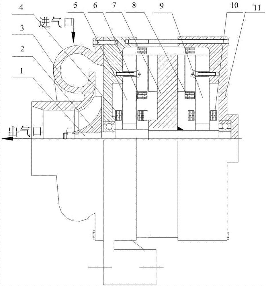
[0038] figure 1 It is a longitudinal sectional view of an electric excitation generator driven by an exhaust gas turbine of the present invention.

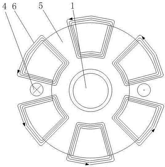
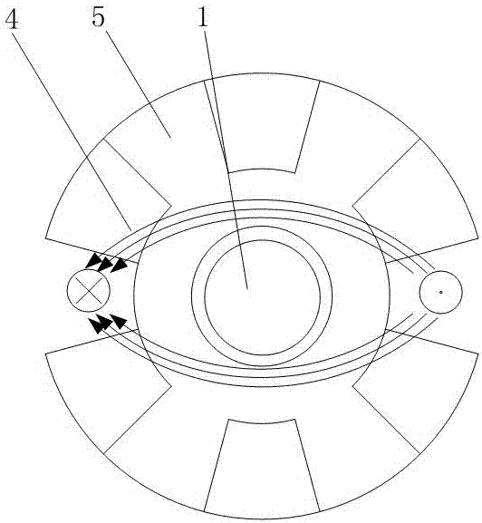
[0039] The exhaust gas turbine drives an electrically excited generator consisting of a shaft (1), an exhaust gas turbine (2), an exhaust gas turbine shell (3), a first field winding (4), a first stator core (5), a first armature winding (6), the rotor core (7), the second armature winding (8), the second stator core (9), the second field winding (10) and the motor casing (11).

[0040] An exhaust gas turbine (2) is fixed at the end of the shaft (1), and a disc-shaped rotor core (7) is fixed in the middle of the shaft (1).

[0041] The rotor core (7) is integrally formed without an excitation source, and under the action of the bearing, the exhaust gas turbine (2) can drive the rotor core (7) to rotate.

[0042] The r...


PUM


Abstract

An exhaust gas turbine-driven electric excitation generator of the present invention is composed of a shaft, an exhaust gas turbine, an exhaust gas turbine shell, two sets of excitation windings, two stator cores, two sets of armature windings, a rotor core and a motor shell. An exhaust gas turbine and a rotor core are respectively fixed on the shaft, and there are rotor poles protruding axially on the two end faces of the rotor core. The stator core is fixed on the inner wall of the casing; the end face of the stator core facing the rotor core has axially protruding stator poles. The armature windings are wound around the stator poles. The excitation winding is wound around the radial direction of the stator core and embedded in the magnetic isolation groove of the stator core. The technical rotor of the present invention is manufactured in one piece and has no excitation winding, which can adapt to the high temperature and high speed working environment of the exhaust gas turbine; it adopts electrified coil excitation, has no positioning torque, and can accelerate rapidly; both ends of the rotor have armatures Winding, the motor has high specific power.

Description

technical field [0001] The invention relates to an electric excitation generator driven by an exhaust gas turbine, which belongs to the technical field of automobile electric appliances. Background technique [0002] At present, thermal power generation uses turbogenerator technology, and the total efficiency of turbogenerators for high-efficiency power generation can be increased to more than 60%-70%. [0003] At present, the thermal efficiency of the engine is mostly below 35%, and the high-temperature and high-pressure exhaust gas discharged by the engine takes away 40% of the thermal energy of the fuel, and most engines cannot effectively use this energy. The exhaust gas turbocharging device realizes the utilization of part of the kinetic energy of the exhaust gas, improves the fuel utilization rate of the engine, and is currently being used more and more widely. [0004] At present, automobile generators are mostly AC generators driven by pulleys, and the power generat...

Claims


Application Information

Patent Timeline
IPC IPC(8): H02K7/18H02K16/04H02K1/22H02K1/24H02K1/14H02K3/28F02B41/10F01D15/10H02P9/48
CPCF01D15/10F02B41/10H02K1/145H02K1/22H02K1/24H02K3/28H02K7/1823H02K16/04H02P9/48Y02T10/12
Inventor 史立伟马永坤聂秀吉马良张学义李金浩
Owner SHANDONG UNIV OF TECH
Why Eureka
Try Eureka