Control circuit for switch power supply

A switching power supply and control circuit technology, applied in control/regulation systems, electrical components, regulating electrical variables, etc., can solve the problems of low safety and reliability, large errors, etc., and achieve high safety and reliability, simple structure, and accurate control. Effect

Inactive Publication Date: 2016-08-24
WEIHAI POWER SUPPLY COMPANY OF STATE GRID SHANDONG ELECTRIC POWER COMPANY
View PDF0 Cites 0 Cited by
  • Summary
  • Abstract
  • Description
  • Claims
  • Application Information

AI Technical Summary

Problems solved by technology

[0003] The technical problem to be solved by the present invention is to provide a simple structure, high safety and reliability and accurate The control circuit of the switching power supply that controls the output voltage

Method used


Image

  • Control circuit for switch power supply

Examples


Embodiment Construction

[0018] A preferred embodiment will be given below, and the present invention will be described more clearly and completely in conjunction with the accompanying drawings.

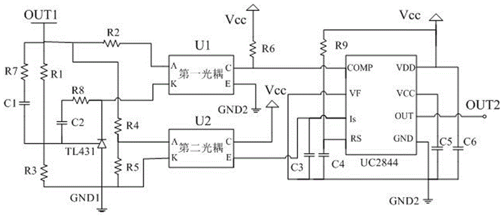
[0019] This embodiment provides a control circuit for a switching power supply, such as figure 1 As shown, including resistor R1, resistor R2, resistor R3, resistor R4, resistor R5, resistor R6, resistor R7, resistor R8, resistor R9, capacitor C1, capacitor C2, capacitor C3, capacitor C4, capacitor C5, capacitor C6, and Regulator TL431, first optocoupler U1, second optocoupler U2 and UC2844 chip;

[0020] The output terminal OUT1 of the switching power supply is electrically connected to one end of the resistor R1, one end of the resistor R2, one end of the resistor R4 and one end of the resistor R7, and the other end of the resistor R2 is electrically connected to the anode A of the first optocoupler U1, and the resistor R7 The other end is electrically connected to one end of the capacitor C1, the cathode...


PUM


Abstract

The invention provides a control circuit for a switch power supply. The output end of the switch power supply is electrically connected with one ends of a first resistor, a second resistor and a fourth resistor separately; the other end of the second resistor is electrically connected with the positive electrode of a first optocoupler; the other end of the first resistor is electrically connected with one end of the third resistor and the reference end of an adjustable voltage stabilizer separately; the negative electrode of the adjustable voltage stabilizer is electrically connected with the negative electrode of the first optocoupler; the other end of the fourth resistor is electrically connected with one end of a fifth resistor and the positive electrode of a second optocoupler separately; the collector electrode of the first optocoupler is electrically connected with a sixth resistor and a compensation end of a UC2844 chip separately; and the output end of the UC2844 chip is electrically connected with a switch tube of the switch power supply. According to the control circuit, the output voltage of the switch power supply is subjected to two-path sampling and isolating; the switch tube of the switch power supply is controlled by the square-wave pulse output by the UC2844 chip, so that accurate control on the output voltage is realized; and in addition, the control circuit is simple in structure and high in safety and reliability.

Description

technical field [0001] The invention relates to the field of switching power supplies, in particular to a control circuit of a switching power supply. Background technique [0002] At present, most of the current signal sampling in the sampling circuit of the switching power supply is sampled through the source series resistance of the switching tube. The sampling current obtained in this way will have a large error when performing precise voltage control. , and the electrical isolation between the output voltage and the control circuit cannot be realized, and the safety and reliability are not high. Contents of the invention [0003] The technical problem to be solved by the present invention is to provide a simple structure, high safety and reliability and accurate A control circuit for a switching power supply that controls the output voltage. [0004] The present invention solves the above technical problems through the following technical solutions: [0005] A cont...

Claims


Application Information

Patent Timeline
Patent Type & Authority Applications(China)
IPC IPC(8): H02M3/156
CPCH02M3/156
Inventor 王阳王冬青邵东强刘宏彬王晓东王锡强张晓臣
Owner WEIHAI POWER SUPPLY COMPANY OF STATE GRID SHANDONG ELECTRIC POWER COMPANY
Why Eureka
Try Eureka