An airborne ultrashortwave antenna

An ultra-short wave and antenna technology, applied in the direction of electrical short antenna, antenna, resonant antenna, etc., can solve the problem of loss of antenna gain, low gain, etc., to achieve the effect of extending the current path, uniform current, and improving communication distance

Active Publication Date: 2022-07-12
XIDIAN UNIV
View PDF9 Cites 0 Cited by
  • Summary
  • Abstract
  • Description
  • Claims
  • Application Information

AI Technical Summary

Problems solved by technology

The loading of the resistance can effectively improve the working bandwidth of the antenna, and even reduce the size of the antenna, but it will lose part of the gain of the antenna
For example, although the well-known 506-3 airborne ultrashort wave antenna has a wide operating bandwidth after being loaded with resistance, its gain is low, and the low frequency gain is only -9dBi

Method used


Image

  • An airborne ultrashortwave antenna
  • An airborne ultrashortwave antenna

Examples


Embodiment 1

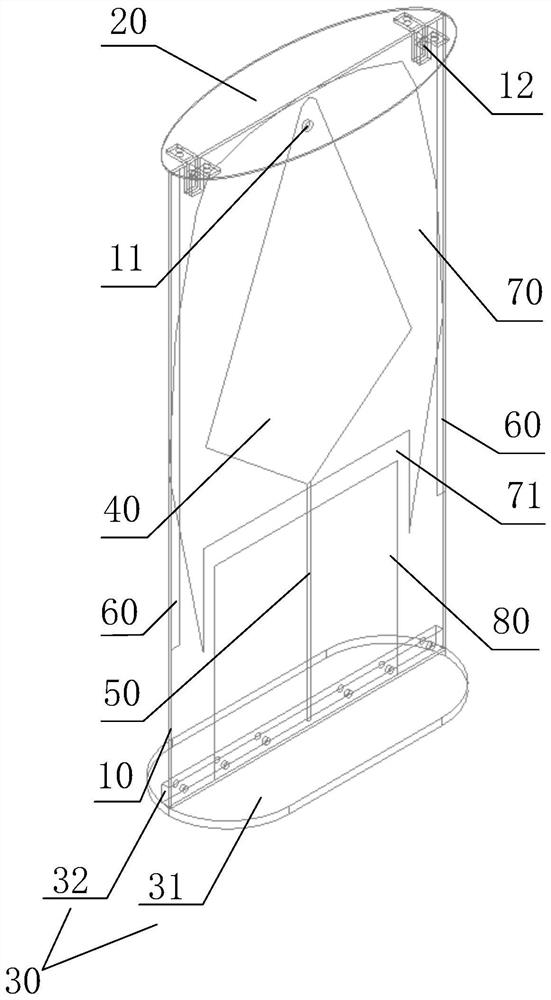
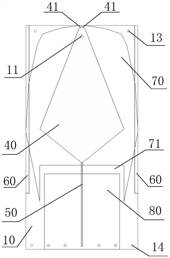
[0037] See figure 1 , an airborne ultrashortwave antenna, comprising: a dielectric plate 10, a first through hole 11, a top loading plate 20, a base 30, a feeding patch 40, a microstrip feeder 50, two branches 60, a radiation patch 70 and a microstrip Floor 80 with feeder. The top end of the medium plate 10 is fixedly connected to the board surface of the top loading plate 20 , and the bottom end of the medium plate 10 is fixedly connected to the base 30 . The top loading plate 20 can make the current on the antenna tend to be uniform, improve the high-frequency impedance characteristics, and its edge capacitance effect improves the low-frequency impedance characteristics, and has the effect of miniaturization. The airborne ultrashortwave antenna takes the central vertical axis of the dielectric plate 10 as the axis-symmetric structure, and the structures on the dielectric plate 10 all take the central vertical axis of the dielectric plate 10 as the axis-symmetric structure. ...


PUM


Abstract

The invention discloses an airborne ultra-short-wave antenna, comprising: a medium plate, a first through hole, a top loading plate, a base, a feeding patch, a microstrip feeder, two branches, a radiation patch and a microstrip feeder floor; a medium board, the top end is fixedly connected with the board surface of the top loading board, and the bottom end is fixedly connected with the base; the feeding patch is set on the front of the dielectric board; the microstrip feeder is set on the front of the dielectric board; The radiation patch is arranged on the back of the dielectric plate; the microstrip feeder floor is arranged on the back of the dielectric plate; the wall of the first through hole is plated with a metal layer. The airborne ultrashort wave antenna of the present invention can not only effectively widen the antenna bandwidth, but also effectively improve the low frequency gain, thereby increasing the communication range of the airborne ultrashort wave system.

Description

technical field [0001] The invention belongs to the technical field of ultrashort wave antennas, and particularly relates to an airborne ultrashort wave antenna. Background technique [0002] In order to ensure the quality of military communication and the confidentiality of information, frequency hopping communication technology is commonly used in the military as an anti-jamming communication technology. Today, frequency hopping technology is developing rapidly in the direction of broadband, low latency, high speed, and low power consumption. As an important part of the wireless communication system, the ultra-short wave antenna, expanding its working bandwidth will enhance the huge role played by the frequency hopping technology in the information warfare. [0003] Ultrashortwave antennas are often designed with wire antennas. The wire antennas have the characteristics of stable performance, simple structure, easy processing and low cost, and are widely used in practical...

Claims


Application Information

Patent Timeline
Patent Type & Authority Patents(China)
IPC IPC(8): H01Q9/04H01Q5/20H01Q5/50H01Q1/48H01Q1/50H01Q1/00H01Q1/28
CPCH01Q9/0457H01Q5/20H01Q5/50H01Q1/48H01Q1/50H01Q1/002H01Q1/285Y02D30/70
Inventor 吴边卢宇锋李军锋何润霏
Owner XIDIAN UNIV
Why Eureka
Try Eureka