A step-by-step method for indoor 3D localization in a multi-floor environment

A three-dimensional positioning, multi-floor technology, applied in positioning, services based on specific environments, services based on location information, etc., can solve the problems of large amount of calculation and low positioning accuracy, and achieve simple layout, high positioning accuracy, and simplification. The effect of the positioning process

Active Publication Date: 2019-04-19
NORTHWESTERN POLYTECHNICAL UNIV
View PDF4 Cites 0 Cited by
  • Summary
  • Abstract
  • Description
  • Claims
  • Application Information

AI Technical Summary

Problems solved by technology

[0005] In order to overcome the deficiencies of the existing technology and solve the problems of large amount of computation and low positioning accuracy encountered in the existing indoor three-dimensional positioning process, the present invention adopts the idea of ​​step-by-step and dimension reduction, and decomposes the three-dimensional positioning into floor positioning and plane positioning. Steps to complete, using the positioning method based on TDOA to achieve accurate positioning of the mobile terminal MT (Mobile Terminal, MT)

Method used


Image

  • A step-by-step method for indoor 3D localization in a multi-floor environment
  • A step-by-step method for indoor 3D localization in a multi-floor environment
  • A step-by-step method for indoor 3D localization in a multi-floor environment

Examples


Embodiment 1

[0086] Example 1: MT3 to be located is located on 3F

[0087] Step 1: Arrangement of AP points in Figure 4 Middle, AP i Represents the distribution of APs. The AP connections on the fourth floor are perpendicular to the floor plane, and all APs are located near the ceiling; MT i Indicates the possible floor position of the positioning MT. 1F, 2F, 3F, and 4F in the figure represent the floor number of each floor, and the floor height h of each floor is 4m; the dotted line position of each floor in the figure is h / 2, 3h / 2, 5h / 2, 7h / 2 Represents the middle position of each floor, that is, the positions where the height values ​​are 2m, 6m, 10m, and 14m respectively. In the case analysis and algorithm analysis measurement, the sandwich between the ceiling and the floor in the actual building is not considered.

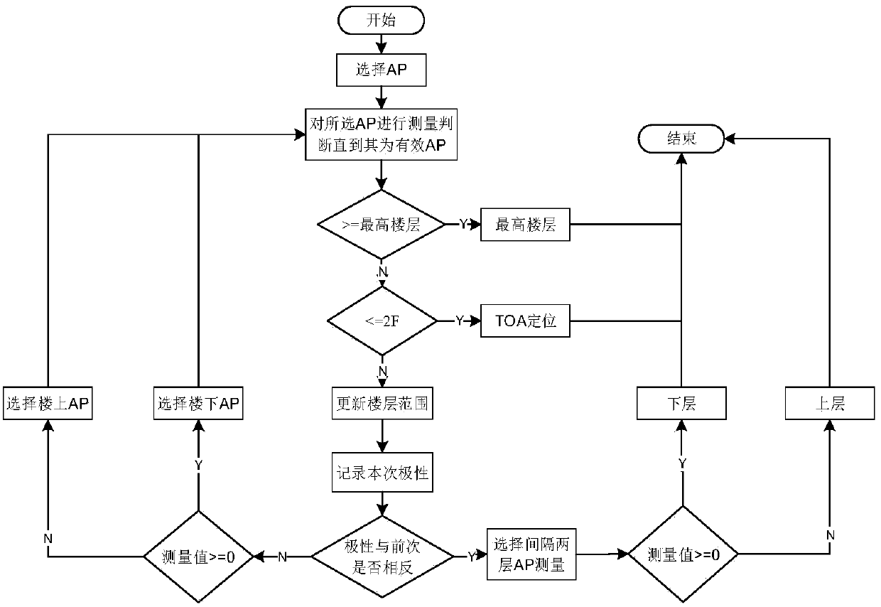
[0088] Step 2: Floor Orientation

[0089] 2.1 The connection line of AP (different floors) is perpendicular to the floor plane of the floor, only considering the cas...

Embodiment 2

[0099] Embodiment 2: The MT4 to be positioned is located on the 4th floor, and the AP setting on the floor is the same as Figure 4 same

[0100] Step 1: Arrangement of AP points in Figure 4 Middle, AP i Represents the distribution of APs. The AP connections on the fourth floor are perpendicular to the floor plane, and all APs are located near the ceiling; MT i Indicates the possible floor position of the positioning MT. 1F, 2F, 3F, and 4F in the figure represent the floor number of each floor, and the floor height h of each floor is 4m; the dotted line position of each floor in the figure is h / 2, 3h / 2, 5h / 2, 7h / 2 Represents the middle position of each floor, that is, the positions where the height values ​​are 2m, 6m, 10m, and 14m respectively. In the case analysis and algorithm analysis measurement, the sandwich between the ceiling and the floor in the actual building is not considered.

[0101] Step 2: Floor Orientation

[0102] 2.1 The connection line of AP (differe...

Embodiment 3

[0110] Step 1: Layout of AP points

[0111] exist Figure 5 , the AP connection line on the fourth floor is not perpendicular to the floor plane; the meanings of other symbols in the figure are the same as Figure 4 same. In the implementation example 3, the MT3 to be located is located on the 3F.

[0112] Step 2: Floor Orientation

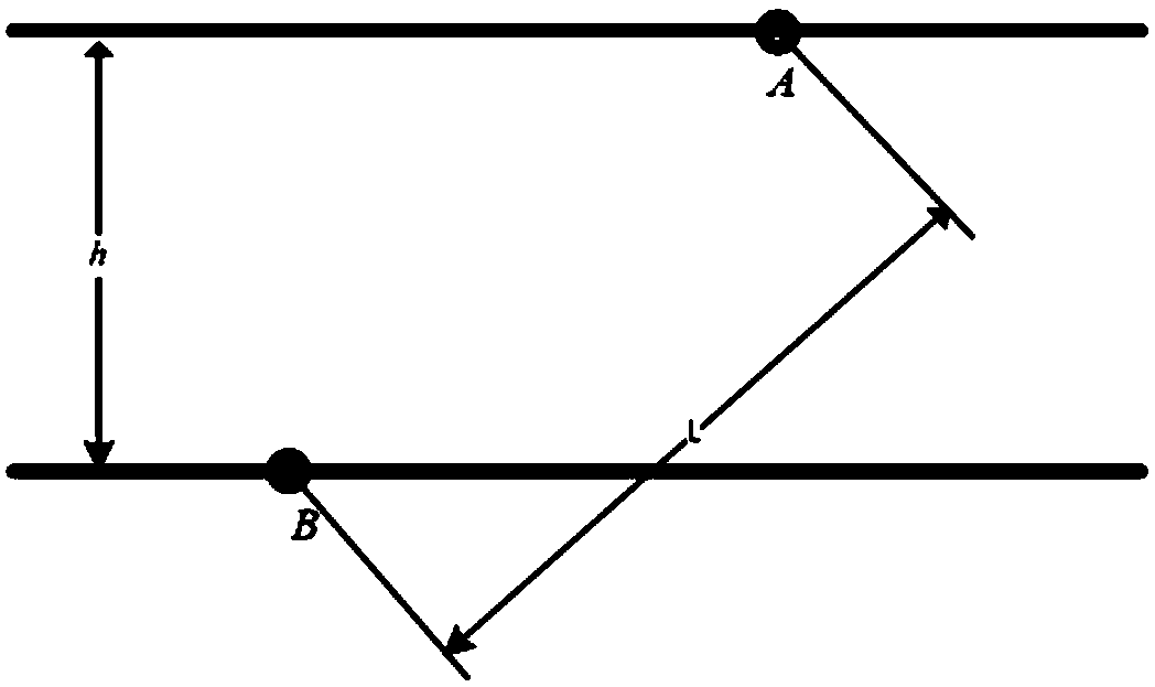
[0113] 2.1 The connection line of AP (different floors) is not perpendicular to the floor plane of the floor (such as Figure 5 );

[0114] 2.2 Select two AP points AP3 and AP4 for judgment, d=3.76m, the distance L between the two APs is 5.7074m, and the floor height h is 4m. Then it is calculated that it does not satisfy the relational expression Therefore, it is necessary to re-select a group of APs on the two floors for re-judgment;

[0115] 2.3 Since AP3 and AP4 do not satisfy the relation Reselect the AP points that can be detected for judgment:

[0116] 2.3.1 Two AP points AP5 and AP6 are selected for judgment, d=4.31m, the distan...


PUM


Abstract

The invention provides a stepwise indoor three-dimensional positioning method for use in a multi-floor environment, and relates to the field of indoor positioning. Three-dimensional positioning is finished through the two steps of floor positioning and plane positioning according to stepwise and dimension reduction thoughts, and accurate positioning of an MT (Mobile Terminal) is realized through a positioning method based on a TDOA (Time Difference of Arrival). The method comprises the following steps: firstly, judging a symbol of a measured value through a judgement mechanism to finish floor positioning of the MT and determine a floor on which the MT is positioned; and then, performing plane positioning on the MT to fulfill the aim of determining the position of the MT. Compared with the prior art, the method has the advantages that three-dimensional positioning of an unknown MT is realized; positioning APs (Access Points) are arranged easily and rapidly; a positioning principle is simple; the positioning accuracy is high; the positioning complexity is low; a database does not need to be pre-established for a multi-floor building to be positioned; a positioning process is simplified; and the portability is high. The method can be applied to various positioning applications of floor information and position information.

Description

technical field [0001] The invention relates to the field of indoor positioning, in particular to a step-by-step method for indoor positioning. Background technique [0002] With the development of wireless communication technology and wireless network, people's demand for positioning, especially indoor positioning is increasing day by day. The indoor scene is relatively complex, with the characteristics of small space and many objects. Therefore, in indoor scenes, it is extremely challenging to obtain the location information of the target. [0003] At present, in the research of indoor positioning technology, the positioning technology of two-dimensional plane is mostly, while the research of indoor positioning technology of three-dimensional space is relatively less. In the actual positioning demand, the indoor positioning technology of two-dimensional plane often cannot meet the positioning needs of users. . Therefore, it is particularly important to study 3D position...

Claims


Application Information

Patent Timeline
Patent Type & Authority Patents(China)
IPC IPC(8): H04W4/02H04W4/33H04W64/00G01S5/02
CPCG01S5/02H04W4/043H04W64/00
Inventor 贺宏锟时雅兵张阳王晓飞许炎
Owner NORTHWESTERN POLYTECHNICAL UNIV
Why Eureka
Try Eureka