
Pneumatic hydraulic pull riveting system

A pneumatic hydraulic and air nozzle technology, applied in the field of hydraulic system, can solve the problems of unstable output pressure, unstable sealing and inflexibility, and achieve the effect of improving work efficiency, large output pressure and ensuring stability

Active Publication Date: 2016-08-31
QINGDAO QIANSHAO PNEUMATIC TOOLS MFG CO LTD
View PDF6 Cites 0 Cited by
  • Summary
  • Abstract
  • Description
  • Claims
  • Application Information

AI Technical Summary

Problems solved by technology

[0002] At present, the existing pumps are large in mass, bulky, bulky, inconvenient to transport and carry, inflexible, inconvenient to maintain, unstable in seal, unstable in output pressure, and low in efficiency.
For example, the aviation hydraulic pump is a hydraulic pump that provides hydraulic oil for the reciprocating motion of the pneumatic tool through a double-acting cylinder. Its power source is 0.49MPa pressure gas, and Kunlun No. The hydraulic pump has the shortcomings of unstable output pressure and low efficiency, and it is large in size, inconvenient to use, inflexible in use, and needs to be improved

Method used


Image

  • Pneumatic hydraulic pull riveting system
  • Pneumatic hydraulic pull riveting system

Examples


Embodiment Construction

[0013] The following will clearly and completely describe the technical solutions in the embodiments of the present invention with reference to the accompanying drawings in the embodiments of the present invention. Obviously, the described embodiments are only some, not all, embodiments of the present invention. Based on the embodiments of the present invention, all other embodiments obtained by persons of ordinary skill in the art without making creative efforts belong to the protection scope of the present invention.

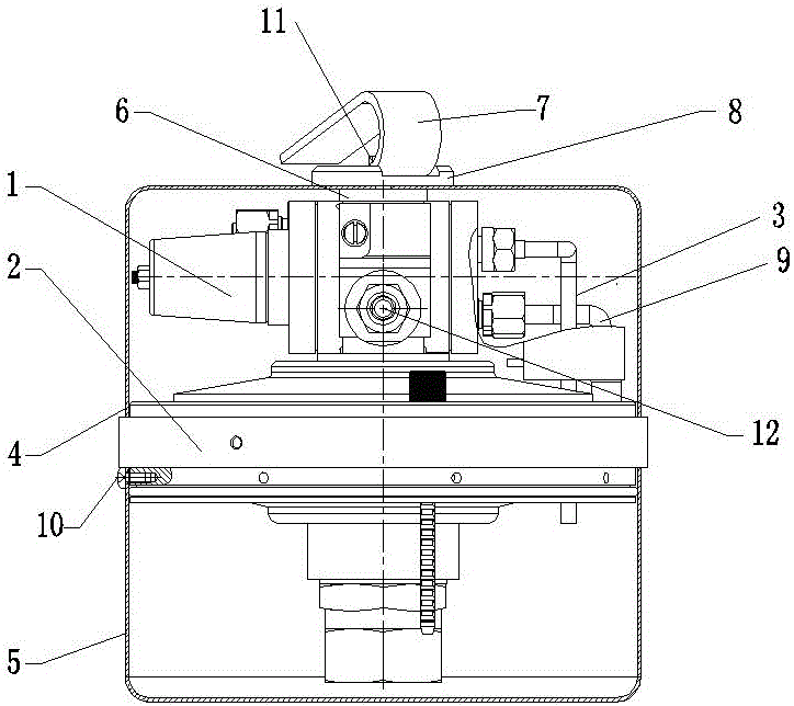
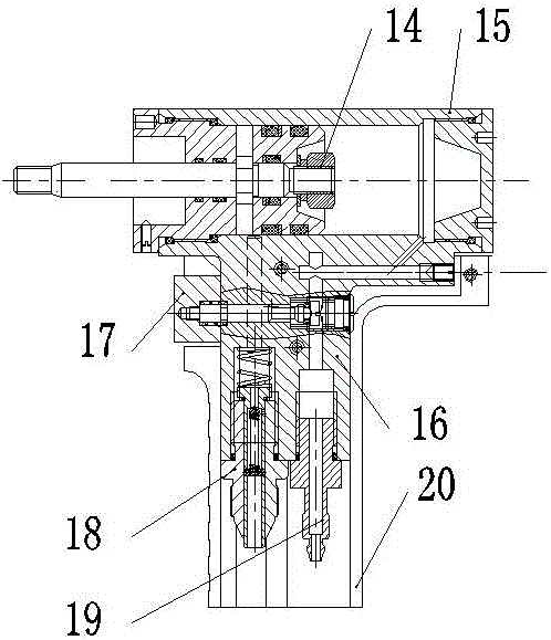
[0014] see Figure 1~2 , In an embodiment of the present invention, a pneumatic hydraulic riveting system includes a control assembly 1 , a piston assembly 2 , an upper casing 4 , an oil tank 5 , a gun piston assembly 14 and a gun barrel 15 . The control assembly 1 is installed on the upper part of the piston assembly 2. The control assembly 1 is also equipped with a nozzle 12. The control assembly 1 is also equipped with an upper oil pipe assembly 3 and an oi...


PUM


Abstract

The invention discloses a pneumatic hydraulic pull riveting system. The system comprises a control assembly, a piston assembly, an upper shell, an oil tank, a pull gun piston assembly and a gun barrel; the control assembly is mounted on the upper portion of the piston assembly, a connecting nozzle is mounted on the control assembly, and an upper oil pipe assembly and an oil returning pipe are mounted on the control assembly; the upper oil pipe assembly and the oil returning pipe are inserted into the lower portion of the piston assembly through reserved through holes to be communicated with the oil tank; a handle gasket ring and a handle seat are mounted at the top end of the upper shell, and a handle hexagonal screw is mounted on the handle seat; a handle is welded to the lower portion of the gun barrel, the pull gun piston assembly is mounted in the gun barrel, a switch valve is arranged on the handle, and an oil nozzle and a gas nozzle which are communicated with the gun barrel are mounted at the lower end of the interior of the handle and are connected with the connecting nozzle through a pipeline; and the system is controlled by a gas path to be on and off, an oil path provides power, the size is small, output pressure is large, parts are sealed through a homemade sealing ring, output hydraulic stability is ensured, carrying and maintaining are convenient, and work efficiency is improved.

Description

technical field [0001] The invention relates to the field of hydraulic systems, in particular to a pneumatic hydraulic riveting system. Background technique [0002] At present, the existing pumps are large in mass, bulky, bulky, inconvenient to transport and carry, inflexible, inconvenient to maintain, unstable in seal, unstable in output pressure, and low in efficiency. For example, an aviation hydraulic pump is a hydraulic pump that provides hydraulic oil for the reciprocating motion of pneumatic tools through a double-acting cylinder. Its power source is 0.49MPa pressure gas, and Kunlun No. 15 aviation hydraulic oil is used as power oil. The hydraulic pump has the shortcomings of unstable output pressure and low efficiency, and it is bulky, inconvenient to use, and inflexible in use, which needs to be improved. Contents of the invention [0003] The purpose of the present invention is to provide a pneumatic hydraulic riveting system to solve the problems raised in the...

Claims


Application Information

Patent Timeline
Patent Type & Authority Applications(China)
IPC IPC(8): B21J15/22B21J15/28
CPCB21J15/22B21J15/28
Inventor 钟毅秦星航解令令韩大尧王朋矫文青王坤
Owner QINGDAO QIANSHAO PNEUMATIC TOOLS MFG CO LTD
Learn More