Meidum- and high-carbon steel plate laser welding method and device
A laser welding, medium and high carbon technology, used in laser welding equipment, welding equipment, welding/welding/cutting items, etc., can solve the problems of poor plasticity and toughness of welds, easy fracture of welds, etc., and achieve the effect of improving welding performance
- Summary
- Abstract
- Description
- Claims
- Application Information
AI Technical Summary
Problems solved by technology
Method used
Image

Examples
Embodiment 1
[0031] A hot-rolled plate with the chemical composition shown in Table 1 is used, and the sample size is: 2.0×500×1000mm, and the welding method is adopted with homogeneous materials.
[0032] Chemical composition (wt%) of table 1 experimental steel
[0033]
[0034] The welding scheme is shown in Table 2. The maximum welding power of the welding machine used here is 12kw CO 2 Laser welding device, the laser power used in this test is 12kw, the welding speed is 6m / min, the welding gap distance is 0.05mm, and the laser focal length is -2.5mm.
[0035] Table 2 welding scheme
[0036]
[0037] Corresponding evaluation experiments were carried out on the welded samples, and the experimental results are shown in Table 3.
[0038] Table 3 Weld quality evaluation
[0039]
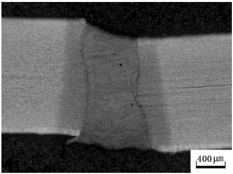
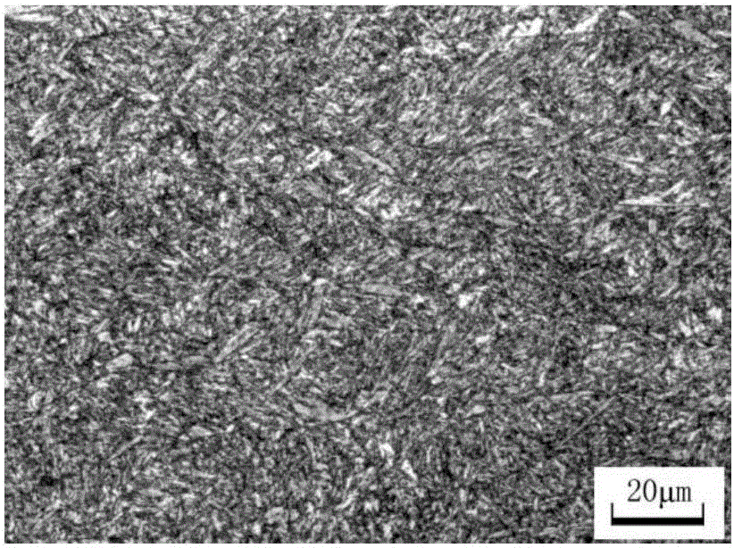
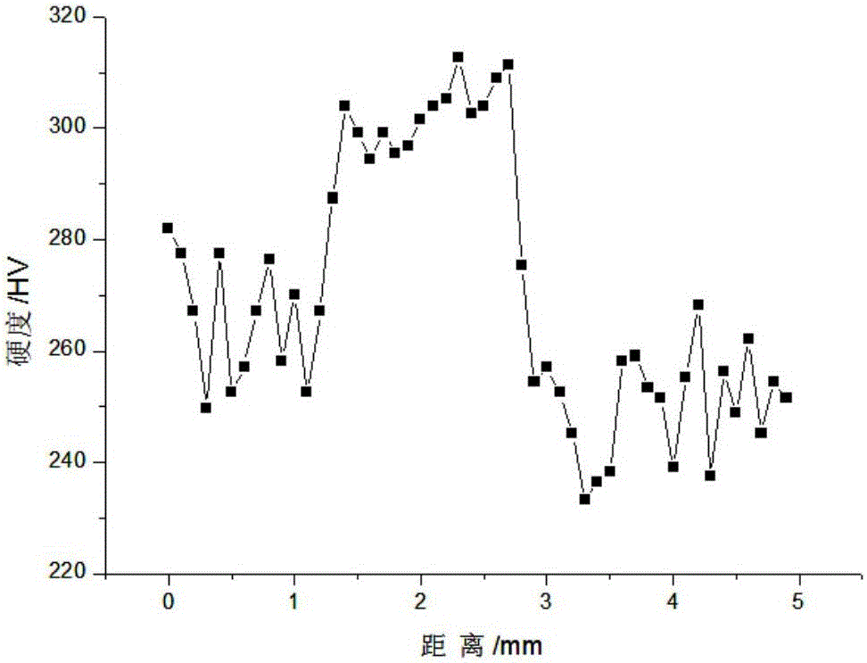
[0040] Observe the weld microstructure after welding, such as figure 1 , figure 2 The tempered sorbite is shown, and the microhardness of the welded structure is tested as image 3 shown.
Embodiment 2
[0042] The hot-rolled plate with the chemical composition shown in Table 4 is used, the sample size is: 2.0×500×1200mm, and the method of welding with homogeneous materials is adopted.
[0043] Chemical composition (wt%) of table 4 experimental steel
[0044]
[0045] The welding scheme is shown in Table 5. The maximum welding power of the welding machine used here is 12kw CO 2 Laser welding device, the laser power used in this test is 8kw, the welding speed is 5m / min, the welding gap distance is 0.06mm, and the laser focal length is -1mm.
[0046] Table 5 welding scheme
[0047]
[0048] Corresponding evaluation experiments were carried out on the welded samples, and the experimental results are shown in Table 6.
[0049] Table 6 Weld quality evaluation
[0050]
[0051] Observe the weld microstructure after welding, such as Figure 4 , Figure 5 The tempered sorbite is shown, and the microhardness of the welded structure is tested as Figure 6 shown.
Embodiment 3
[0053] Use a hot-rolled plate with the chemical composition shown in Table 7. The sample size is: 2.0×500×1200mm, and the method of welding with homogeneous materials is adopted.
[0054] Chemical composition (wt%) of table 7 experimental steel
[0055]
[0056] The welding scheme is shown in Table 8. The maximum welding power of the welding machine used here is 12kw CO 2 Laser welding device, the laser power used in this test is 6kw, the welding speed is 4m / min, the welding gap distance is 0.08mm, and the laser focal length is -0.5mm.
[0057] Table 7 welding scheme
[0058]
[0059] Corresponding evaluation experiments were carried out on the welded samples, and the experimental results are shown in Table 6.
[0060] Table 8 Weld Quality Evaluation
[0061]
[0062] Observe the weld microstructure after welding, such as Figure 7 , Figure 8 The tempered sorbite is shown, and the microhardness of the welded structure is tested as Figure 9 shown.
[0063]From...
PUM
| Property | Measurement | Unit |
|---|---|---|
| Thickness | aaaaa | aaaaa |
Abstract
Description
Claims
Application Information
 - Generate Ideas
- Intellectual Property
- Life Sciences
- Materials
- Tech Scout
- Unparalleled Data Quality
- Higher Quality Content
- 60% Fewer Hallucinations
Browse by: Latest US Patents, China's latest patents, Technical Efficacy Thesaurus, Application Domain, Technology Topic, Popular Technical Reports.
© 2025 PatSnap. All rights reserved.Legal|Privacy policy|Modern Slavery Act Transparency Statement|Sitemap|About US| Contact US: help@patsnap.com