Supercharge Your Innovation With Domain-Expert AI Agents!

A hydraulic vulcanizing machine mold adjusting force device and hydraulic vulcanizing machine

A technology of mold adjustment and afterburner and vulcanizer, applied in the field of tire machinery, can solve the problems of increased manufacturing cost, large force deformation, mold adjustment height error, etc., and achieves the effect of reducing processing and manufacturing cost, improving equipment performance and simple structure

Active Publication Date: 2018-03-09
SAFE RUN & HISCENT MACHINERY SUZHOU
View PDF8 Cites 0 Cited by
  • Summary
  • Abstract
  • Description
  • Claims
  • Application Information

AI Technical Summary

Problems solved by technology

In this method of mold adjustment through thread pairs, since the mold adjustment nut is fixed to the booster column, the mold adjustment nut needs to be driven by the booster cylinder connected to the booster column. However, this will not only make the mold adjustment Errors in the height will weaken the force strength of the mold-adjusting studs, and will also increase the fit gap in the thread pair, making it easier for impurities to enter; or it may be difficult to adjust due to the sintering of lubricating oil
In addition, the frame of the frame-type hydraulic vulcanizing machine needs to bear all the reaction force of clamping mold, and the force deformation is large, so the strength of the fuselage needs to be strengthened, resulting in a serious increase in manufacturing costs

Method used


Image

  • A hydraulic vulcanizing machine mold adjusting force device and hydraulic vulcanizing machine
  • A hydraulic vulcanizing machine mold adjusting force device and hydraulic vulcanizing machine

Examples


Embodiment Construction

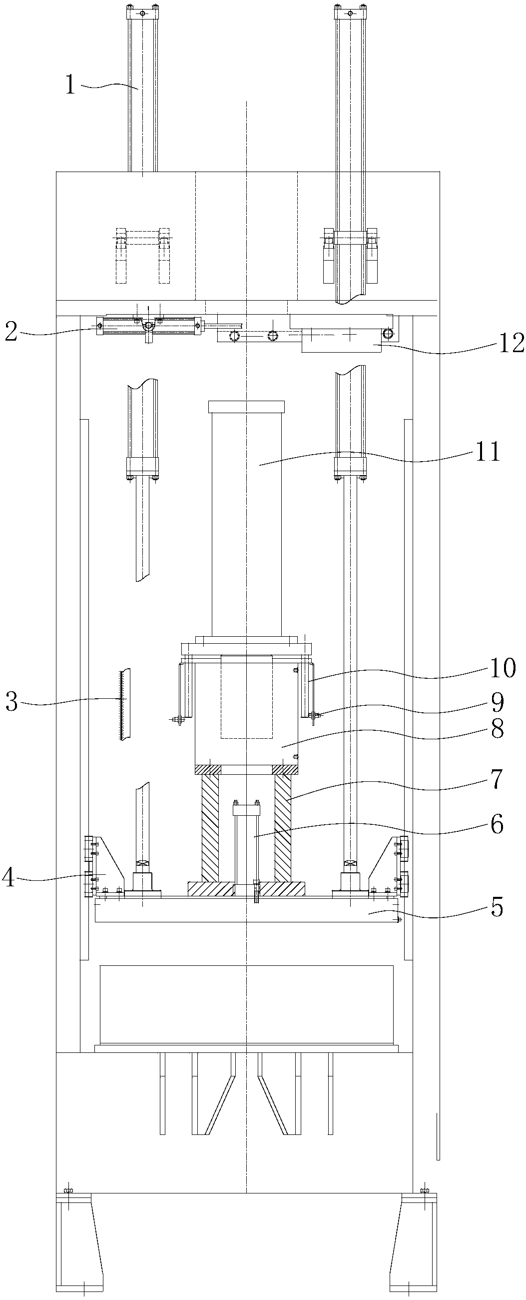
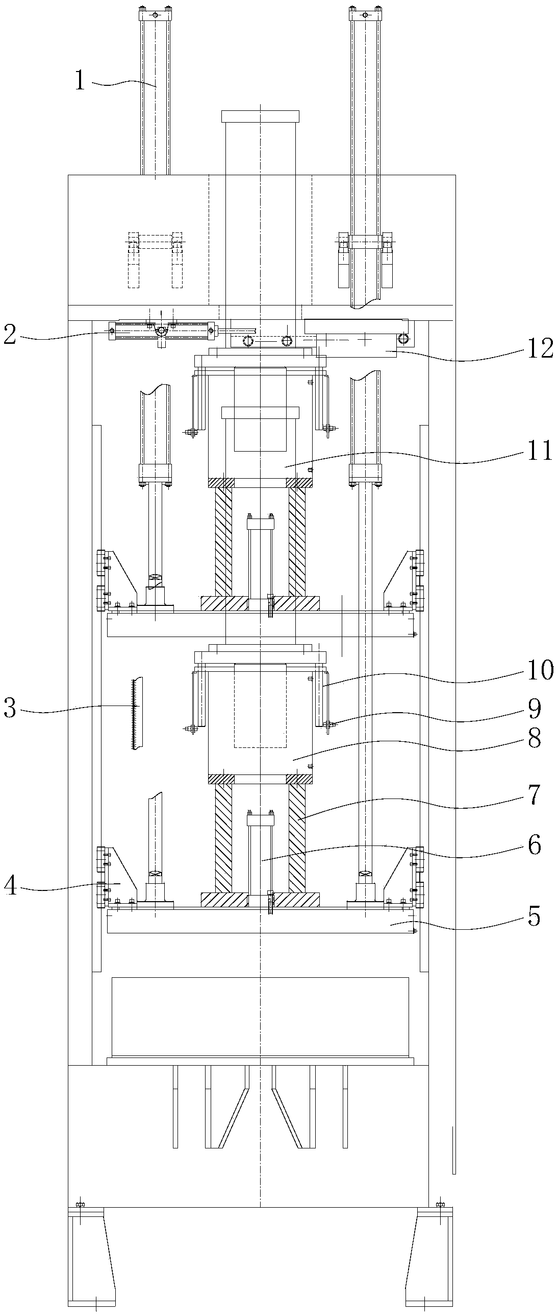
[0022] The technical solutions of the present invention will be further described below in conjunction with the accompanying drawings and through specific implementation methods.

[0023] Such as figure 1 As shown, a hydraulic vulcanizer mold adjusting force device of the present invention includes an upper supporting plate 5 that is horizontally arranged below the beam of the main frame and can slide up and down with the main frame, the top of the upper supporting plate 5 and the main frame The top mold opening and closing cylinder 1 is connected, wherein the bottom of the opening and closing mold cylinder 1 is connected with a mold opening and closing ejector pin, and the mold opening and closing mold ejector is connected with a column, and the column is connected with the upper support plate 5 The top is connected; the side of the upper supporting plate 5 is connected with a slider 4, and the slider 4 is slidably connected with the main frame.

[0024] The top of the upper...


PUM


Abstract

The invention discloses a die adjustment and force application device for a hydraulic vulcanizing machine, and a hydraulic vulcanizing machine. The die adjustment and force application device for the hydraulic vulcanizing machine comprises an upper support plate, wherein the top of the upper support plate is connected with a die opening-closing oil cylinder at the top of a main machine frame; a segmented die oil cylinder and a lower support seat are arranged at the top of the upper support plate, the segmented die oil cylinder is connected with a segmented die, the lower support seat is arranged around the segmented die oil cylinder, a die adjustment and force application oil cylinder is connected to the top of the lower support seat, and a force application ejection rod is connected to the top of the die adjustment and force application oil cylinder. The die adjustment and force application device for the hydraulic vulcanizing machine further comprises a force application ejection plate, wherein the force application ejection plate is connected with an air cylinder, and the force application ejection plate is capable of horizontally moving with the horizontal telescoping of the air cylinder; the force application ejection plate is removed out to be staggered with the force application ejection rod during die opening of the hydraulic vulcanizing machine; and the force application ejection plate is returned and the force application ejection rod is abutted against the force application ejection plate during die closing of the hydraulic vulcanizing machine. The die adjustment and force application device for the hydraulic vulcanizing machine enables die adjustment and force application to realize drive through one oil cylinder, is simpler in structure and simple and convenient to operate, reduces the machining and manufacturing cost, and improves the equipment performance.

Description

technical field [0001] The invention relates to the technical field of tire machinery, in particular to a mold adjusting force device for a hydraulic vulcanizer and a hydraulic vulcanizer. Background technique [0002] The hydraulic vulcanizing press is the equipment used to complete the last process of tire production, and is the key equipment to determine the quality of tires. The more common frame-type hydraulic vulcanizing machine consists of a main engine frame, afterburner cylinder, afterburner column, afterburner top plate, upper support plate, etc. to form a closed force system, which is used to ensure the tensile force required for tire vulcanization. It is the typical structural feature of the frame-type hydraulic vulcanizing machine. When it works: the tire is placed in the curing chamber, the curing chamber is fixed on the upper pallet, and the movable mold cylinder is installed on the upper pallet. The movable mold cylinder is used for tire pattern forming. Mol...

Claims


Application Information

Patent Timeline
Patent Type & Authority Patents(China)
IPC IPC(8): B29C35/02B29D30/06
CPCB29C35/02B29D30/0601
Inventor 邓海珊
Owner SAFE RUN & HISCENT MACHINERY SUZHOU
Features
  • R&D
  • Intellectual Property
  • Life Sciences
  • Materials
  • Tech Scout
  • Unparalleled Data Quality
  • Higher Quality Content
  • 60% Fewer Hallucinations
Learn More